
Operating instructions


7
Installation
MOUNTING
Mount the unit in a DRY location. Allow at least 1 inch of clearance for adequate cooling.
POWER CONNECTION
The unit is supplied with three foot power input leads. This should normally be adequate to
connect to a source of power. If you must extend the cable:
• Use the smallest extension length possible.
• Use no less than 10 gauge conductors.
• Splice and solder the joints.
• Protect the joints with heat shrink tubing.
Connect the wires as follows:
• Red to Positive
• Black to Negative
OUTPUT CONNECTIONS
Two positive output terminals and two negative output terminals are provided. Connect only
one wire to each terminal. A jumper externally connects the positive terminals of the BCD605-
12-24. This jumper may be removed and the BCD605-12-24 used as a dual bank charger if and
only if the input voltage is less than 15 volts.
Note that the current specications are for input current. To obtain the maximum output
current capability at any given input voltage, use the following formula:
Output Current = Input Volts / Output Volts x 40
For example:
11 VDC in and 27 VDC out, the max output current = 11/27 x 40 = 16.3 Amps.
20 VDC in and 27 VDC out, the max output current = 20/27 x 40 = 29.6 Amps
Each output terminal can supply up to 25 Amps, therefore do not connect more than 25 amps
of load to either output terminal. If the load exceeds 25 Amps but not the continuous rated
output of the unit, do the following: The output terminals must be connected to the load in
parallel ensuring that the wiring used has sufcient capacity to handle the current.
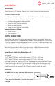
PLEASE NOTE:
The BCD605-12-12 is a single bank charger ONLY and must be
hooked up as shown in the drawing to the right!
The BCD605-12-24 may be used as a dual bank charger if the
input voltage is less than 15 volts! If the input is greater than
15 volts the unit must be hooked up as shown in the drawing
to the right!