
Product Manual


9
If the red Charging LED, the Low Output LED and the audible alarm come on, and the green
Output On LED is completely off, the output of the unit has been shorted out, or there has been
an internal failure. Turn the unit off, disconnect the battery bank connected to it, and turn
it back on again. If it comes on normally, then the battery bank or output connections have
a short. You must rectify the cause of the fault before reconnecting the battery bank. If the
condition still exists after the battery bank has been disconnected, the unit is defective, and
must be returned to the factory or an authorized service center for repair.
If the unit will not turn on at all, check the input fuse. If it is blown, replace it with a new one.
If that fuse blows as well or the unit still will not turn on, it is defective, and must be returned
to the factory or an authorized service center for repair.
If the green ‘Output On’ LED is on, but there is no voltage at the output terminals, check the
output fuses. If they are blown, replace them with AGC 30A fuses. If there is still no voltage
at the terminals, the unit is defective, and must be returned to the factory or an authorized
service center for repair.
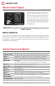
Dry Contact Relay
To use your dry contact output fail relay you must connect a 9-pin D connector to the unit. You
must use pins one and six as is indicated on page 8 in the remote control diagram.
The relay is factory preset to fail in the closed position when the low output LED and buzzer
come on. If you wish to have the relay fail in the open position when the low output LED
and buzzer come on, you must take the cover off the unit and move the jumper to the other
position on J5. J5 is located next to the relay.To change the position of the jumper, rst turn
the unit off and disconnect the unit from both the power and batteries. Next, turn the unit on
for 30 seconds to discharge the capacitors, then turn it off again. Turn the unit upside down
and remove the four screws. Remove the cover and locate J5. It will be next to the relay as
is shown in the above diagram. Simply move the jumper to the desired position as is shown
in the above diagram. Replace the cover and re-install the four screws. Reconnect the unit to
the power and batteries.