
Product Manual


11
Meters
A high quality digital meter can be added to the voltage converter (factory installed only).
The meter shows simultaneous voltage and current on either of the two output terminals. A
toggle switch permits selection between the output terminals. The meter features bright red
LED readouts to permit easy monitoring from many feet or meters away.
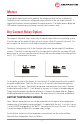
Dry Contact Relay Option
The charger is tted with a dry contact relay to indicate output failure to a monitoring system.
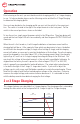
To use the dry contact output fail relay you must connect a 9-pin D connector to the unit. You
must use pins one and six as is indicated on the remote connector diagram.
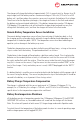
The relay is factory preset to fail in the closed position when the low output LED and buzzer
come on. If you wish to have the relay fail in the open position when the low output LED and
buzzer come on, you must take the cover off the unit and move the jumper to the other position
on J11. J11 is located next to the relay.
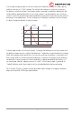
To change the position of the jumper, rst turn the unit off and disconnect the unit from both
the power and batteries. Next, turn the unit on for 30 seconds to discharge the capacitors,
and then turn it off again. Turn the unit upside down and remove the four screws. Remove
the base plate and locate J11. It will be next to the relay as is shown in the above diagram.
Simply move the jumper to the desired position as is shown in the above diagram. Replace
the base plate and re-install the four screws. Reconnect the unit to the power and batteries.
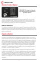
BATTERY TEMPERATURE SENSORS
Up to 2 battery temperature sensors can be connected to the charger to allow temperature
compensation of the battery charging voltage (1 is supplied with the unit). If only the 1 sensor
is used, it MUST be plugged into the ‘BATT 1’ connection on the front of the unit. If no sensor
is used, the charger will default to standard output voltage.
For installation instructions of the temperature sensor, please see the section entitled
Remote Battery Temperature Sensor Installation.