USER MANUAL Version 5.
THANK YOU By following these simple steps you will be able to obtain the most from your powerful Di-VentiX II and its many features. TABLE OF CONTENTS 1 INTRODUCTION 4 1-1. Di-VentiX II OPERATING MODES 4 Mixer Mode Embedded Soft Edge Mode Sync Matrix Mode 1-2. USEFUL TERMS AND DEFINITIONS HARDWARE INSTALLATION 5 6 2-1. SAFETY INSTRUCTIONS 6 2-2. UNPACKING AND INSPECTION 11 2-3. RACKMOUNT INFORMATION 11 2-4. CABLE & ADAPTOR INFORMATION 11 2-5.
OPERATING THE Di-VentiX II 4-1. THE Di-VentiX II FRONT PANEL 26 26 Overview Menu section Input/Frame section Layer section Layer adjust section User Preset section Take and Stepback section 4-2. THE Di-VentiX II MENU 29 Menu navigation Home menu 4-3.
-2. WORKING WITH THE RCS (continued) 57 Memorizing MaskFrame MemorizingLogos Control Menu Embedded Edge Blending Mode with RCS OPTIONAL REMOTE CONTROL SYSTEMS 62 6-1. Axion2 - Ref. ARC200 62 6-2. Orchestra - Ref. ORC50 62 6-3. Remote Keypad - Ref. RKD8044-T 62 EXAMPLES AND TIPS 63 7-1. ABOUT EXAMPLES 63 7-2. EXAMPLES 63 7-3. EXTERNAL PROGRAMMING 69 SOFT EDGE BLENDING SOFT EDGE BLENDING (SEB) SETUP APPENDIX 70 70 73 A. Di-VentiX II HDCP Management 73 B.
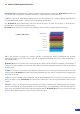
INTRODUCTION 1-1. THE Di-VentiX II OPERATING MODES Before you set up your Di-VentiX II for the first time, be sure you know exactly what you want to do with it. The Di-VentiX II offers a choice of three operating modes, which results in a versatile video production tool for live event staging and fixed installation applications. * NOTE * : We recommend resetting the device to its default values every time you set up your shows or events (see the “Operating The Di-VentiX II” chapter, p26).
1-2. USEFUL TERMS AND DEFINITIONS BACKGROUND: a Background is a source, typically originating from a computer. Di-VentiX II enables you to work with live or still (frame) background sources - visually behind all other sources. LAYER: a Layer is an image display element (such as a PIP window, Key, Logo(s) or Background) that has an associated visual priority — either in front of or behind another layer.
HARDWARE INSTALLATION 2-1. SAFETY INSTRUCTIONS CAUTION: All of the safety and operating instructions should be read before the product is operated and should be maintained for further reference. Please follow all the warnings regarding this product and its operating instructions. • WARNING: To prevent the risk of electric shock and fire, do not expose the device to rain, humidity, intense heat sources (such as heaters and direct sunlight).
INSTRUCTIONS DE SECURITE Afin de mieux comprendre le fonctionnement de cet appareil nous vous conseillons de bien lire toutes les consignes de sécurité et de fonctionnement de l’appareil avant utilisation. Conservez les instructions de sécurité et de fonctionnement afin de pouvoir les consulter ultérieurement. Respectez toutes les consignes marquées dans la documentation, sur le produit et sur ce document.
INSTRUZIONI DI SECUREZZA Allo scopo di capire meglio il funzionamento di questa apparecchiatura vi consigliamo di leggere bene tutti i consigli di sicurezza e di funzionamento prima dell’utilizzo. Conservare le istruzioni di sicurezza e di funzionamento al fine di poterle consultare ulteriormente. Seguire tutti i consigli indicati su questo manuale e sull’apparecchiatura.
SICHERHEITSHINWEISE Um den Betrieb dieses Geräts zu verstehen, raten wir Ihnen vor der Inbetriebnahme alle Sicherheits und Betriebsanweisungen genau zu lesen. Diese Sicherheits- und Betriebsanweisungen für einen späteren Gebrauch sicher aufbewahren. Alle in den Unterlagen, an dem Gerät und hier angegebenen Sicherheitsanweisungen einhalten. • ACHTUNG: um jegliches Risiko eines Stromschlags oder Feuers zu vermeiden, das Gerät nicht Regen, Feuchtigkeit oder intensiven Wärmequellen aussetzen.
INSTRUCCIONES DE SEGURIDAD Para comprender mejor el funcionamiento de este aparato, le recomendamos que le acuidadosamente todas las consignas de seguridad y de funcionamiento del aparato antes de usarlo. Conserve las instrucciones de seguridad y de funcionamiento para que pueda consultarlas posteriormente. Respete todas las consignas indicadas en la documentación, relacionadas con el producto y este documento.
2-2. UNPACKING AND INSPECTION Please ensure that the following items have been delivered with your Di-VentiX II. 1 x Di-VentiX II (DVX8044) 1 x Power supply cord 1 x MCO 8 Pin Connector 1 x RCS - Remote Control Software * 1 x User Manual (PDF Version) * 1 x Quick Start Guide * * Download from our website: www.analogway.com 2-3. MOUNTING INFORMATION Tabletop mounting: The Di-VentiX II can be used directly on a table, the unit is equipped with 4 handy anti-slip rubber feet.
2-5. HARDWARE SPECIFICATIONS Input specifications • ANALOG COMPUTER: Connectors: Inputs #1 to #8: Female HD15, DVI-I, and 4x BNC. Line frequency: Up to 130 kHz (165 MHz Max pixel rate). Resolution: Up to 1600x1200px @ 165Mhz, 1920x1200px (RB, Max V size : 1200px, Max H size 2048px). Sync. types: RGBHV, RGB/S, RGsB (Sync On Green). Levels: R, G, B = 0.7 Vp/p. H & V Sync = TTL Composite Sync = TTL and 0.3 V (negative). SOG (Sync On Green) = 0.3 V. Impedance: R, G, B = 75 ohms.
• COMPOSITE VIDEO: Connectors: Inputs #1 to #8: Female HD15, DVI-I, 1x BNC. Standard: PAL / SECAM: 15.625 kHz - 50 Hz - 625 lines. NTSC (3.58 - 4.43 MHz): 15.734 kHz/60 Hz/525 lines. Level: 1 Vp/p (0.7 V Luma + 0.3 V Sync.). Impedance: 75 ohms. or or • DVI (Digital Video Interface): Connector: Inputs #1 to #4: Female DVI-I. Line frequency: Up to 130 kHz (165 MHz Max pixel rate). Format: Digital Visual Interface (DVI)-TMDS single link.
• ANALOG OUTPUTS: Connector: Output #1 (Main): Female HD15, 5 x BNC, Analog part of the DVI-I Output #2 (Preview): Female HD15, 5 x BNC, Analog part of the DVI-I.
• DVI (Digital Video Interface) OUTPUTS: Connector: Outputs #1 (Main) & #2 (Preview): Female DVI-I. Signal: Digital Visual Interface (DVI)-TMDS single link.
• GENLOCK: Connectors: 2 x Female BNC (in & out). Function: available only in framelock mode. Analog SD or HD active loopthrough. • DEVICE SYNC: Connectors: RJ45 Protocol: Proprietary Protocol. Function: S ynchronisation of several machines (multi machine Soft Edge Blending).
Formats: Format Ratio Refresh Rate SDTV PAL 4:3 50Hz SDTV NTSC 4:3 59,94Hz EDTV 480p 4:3 59,94Hz EDTV 576p 4:3 50Hz HDTV 720p 16 : 9 50Hz 59,94Hz 60Hz HDTV 1035i 16 : 9 59,94Hz 60Hz HDTV 1080i 16 : 9 50Hz 59,94Hz 60Hz HDTV 1080p 16 : 9 23,97Hz 24Hz 25Hz 29,97Hz 30Hz HDTV 1080sF 16 : 9 50Hz 59,94Hz 60Hz 4:3 50Hz 60Hz 72Hz 75Hz 800 x 600 4:3 50Hz 60Hz 72Hz 75Hz 848 x 480 16 : 9 50Hz 60Hz 72Hz 75Hz 1024 x 768 4:3 50Hz 60Hz 72Hz 75Hz 1280 x 720 16 : 9 50Hz 60Hz 1280 x
Pinouts • VGA STANDARD VGA 1- Red 2- Green 3- Blue 4- ID Bit 2 5- Test (Gnd) 6- Red Return 7- Green Return 8- Blue Return 9- No Pin 10- Sync Return • DIGITAL VISUAL INTERFACE DVI Pin 1- TMDS Data 27- DDC Data 2- TMDS Data 2+ 8- Analog Vertical Sync 3- TMDS Data 2 Shield 9- TMDS Data 1- 4- Not used 10- TMDS Data 1+ 5- Not used 11- TMDS Data 1 Shield 6- DDC Clock 12- Not used 11- ID Bit 0 12- ID Bit 1 13- H Sync 14- V Sync 15- ID Bit 3 13- Not used 14- +5V (Powe
HDCP compliance If you want to use HDCP content (High-bandwidth Digital Content Protection) from your sources, make sure that you use HDCP compliant screens or projectors. If not, your image could be disabled.
CONNECTING THE DI-VENTIX II 3-1. CONNECTING THE Di-VentiX II The Di-VentiX II can be set up with up to 8 different sources, and will drive up to 4 digital DVI-HD/SD-SDI sources and 4 analog computer/video sources simultaneously. The versatility of the Di-VentiX II will allow for almost any event configuration and cater for all your projection needs. The intuitive rear panel of the Di-VentiX II will let you set up for the first time quickly and easily. Here is an example of a typical Di-VentiX II setup.
3-2. THE DI-VENTIX II REAR PANEL Overview The Di-VentiX II rear panel is equipped with 8 universal digital and analog inputs. Inputs #1 through #4 (2) are universal digital and analog inputs. Inputs #5 through #8 (3) are universal analog inputs (see also Input Specifications in this chapter). The Main (4) and Preview (5) outputs will allow for the Di-VentiX II high resolution digital and analog signals to be viewed on screen and/or on a preview monitor (see also “Output Specifications” in this chapter).
Inputs #1 to #4 SD/HD-SDI, DVI AND ANALOG SOURCES: Inputs #1 to #4 on the Di-VentiX II accept up to 4 live sources in Digital and analog formats. SD/HD-SDI: 1 x digital input on female BNC connector. DVI-I: 1 x digital (DVI) and 1 x analog input on female DVI-I universal connector. * NOTE * : SDI and DVI entries cannot be used simultaneously on a single input.
S.VIDEO SOURCES: The S.VIDEO signal, also called Y/C, HI-8™, or S.VHS™, is available on DVD players and high quality VCRs (S.VHS). The S.VIDEO signal in which the Luminance (Y) and Chrominance (C) information are separately transmitted, gives a higher quality picture than the Composite video signal. Connections: 1 x 4pin mini-Din --> 2 x Female BNC (C & Y) 2 x BNC (R & G) --> 1 x Female HD15.
Preview Outputs PREVIEW OUTPUT: DIGITAL: 1 x digital (HD-SDI) output for the main display device on female BNC connector. This output is compatible in 3G-SDI. ANALOG: 1 x analog output for the main display device on female HD15 connector. UNIVERSAL: 1 x analog output for the main display device on 5 x female BNC connectors. DIGITAL/ANALOG: 2 x main output on female DVI-I connector (simultaneous analog and digital).
AUDIO SWITCHER OPTION – OPT-8044A: Audio Stereo Switcher card features 8 inputs and 2 outputs. An auxiliary input can be mixed with any other input. Master Volume and individual input level can be adjusted. Each input and output offers balanced or unbalanced connections. It should be noted that the management of the audio output follows the position of video layers. Two modes are available: Follow or Breakaway. In Follow Mode the audio follows the last active video layer (after having pressed [TAKE]).
OPERATING THE Di-VentiX II 4-1. THE Di-VentiX II FRONT PANEL Overview The highly intuitive front panel of the Di-VentiX II was designed by Analog Way engineers to simply and quickly meet all of your event needs. Within minutes, you will be able to enjoy its full potential and easily parameter most of its functions, without having to be an expert audio-visual engineer, leaving room for what is most important to our users: concentrating on their event.
Menu section The «Menu» section of the Di-VentiX II gives you access to all the machine’s setup functions, parameters and tweaks, and is the starting point to any of the machine’s endless setup capabilities. Here, you will easily find and select functions and parameters, quickly scroll through the extensive choices with the four practical selection knobs, and set values with the four corresponding [SET] buttons.
User Preset section The user «Preset» section allows users to quickly create, select and use presets for complex show animations and stunning transitions. Simply select the desired preset to use it immediately in your show, or preview it to tweak any of its parameters. The [SHIFT] button will allow for the «Preset» buttons to toggle between presets #1 and #3, or #2 and #4.
4-2. THE DI-VENTIX II MENU Menu navigation To access the Di-VentiX II menu, in the menu section, simply press the [EXIT/MENU] button (1). To highlight items in the menu which will appear on the VFD screen (4), turn the corresponding knob (2) left or right to the desired menu item. When you have reached the desired menu item, press the corresponding [SET] button (3) to access that menu function.
4-3. WORKING WITH THE DI-VENTIX II Operating Modes The Di-VentiX II offers three modes to work from: - the Mixer mode, which is the Di-VentiX II default mode, - the Embedded Soft Edge Blending mode, which will allow you to blend two video projection sources together to obtain one smooth image on screen, and - the Sync Matrix mode, which turns your Di-VentiX II into a true 8 x 2 scaled matrix.
Di-VentiX II color codes Analog Way engineers have developped a handy, user friendly way of identifying machine status on the front panel, via the use of color codes on the buttons of the machine. All new Analog Way machines use the same codes, for quick recognition of the status of any device of the range, at any given time. For the Di-VentiX II, button color codes are as follows: - Main sources section are indicated in red. - Preview sources section are indicated in green.
Source output selection Once your inputs have all been configured, the output settings of the Di-VentiX II must be set according to the machines plugged into your Di-VentiX II main and preview outputs (video projector, preview monitor...). * IMPORTANT * : it is strongly recommended to set the output format of the Di-VentiX II to match the native resolution of the display devices connected to the Di-VentiX II.
Working with Layers The use of layers on the Di-VentiX II will help you to create stunning shows by fine tuning all the parameters of any of your sources to achieve what it is you want to do with your Di-VentiX II. Once your inputs have all been configured, you can affect them to any of the four available layers to position them on the screen, size them, adjust color and transparency, use or create presets to animate them (see also “Working With Layer Functions”, p34).
Working with Layer functions Once source and layer attributes have been set, you can start working with layer functions. Layer functions allow you to fine tune and stylize individual layers by adding effects and programming movement, transitions, opening and closing effects. In the following example, we shall see how to create a layer opening effect. 1/ In the «Layer» section, press the layer button of the layer you wish to work with (A-D). The layer button will start blinking.
PIP configuration 1/ In the «Layer» section, press the layer button of the layer you wish to turn into a PIP (A-D). The button will start blinking. On the preview screen, the layer will appear as a blinking color rectangle, and the selected layer letter will be indicated in the layer rectangle. Layer parameters will appear on your menu screen once a source has been affected to that layer.
4/ Select Record Frames from the Logo/Frames menu by rotating the corresponding knob, then pressing the corresponding [SET] button. A white rectangle will appear on your main display, indicating the frame which will be captured. Select an empty frame memory (empty frames are indicated in the sub-menu) to store the frame into. Press the corresponding [SET] button. 5/ Select Yes with the corresponding knob when the LCD screen asks for frame record confirmation, then press the corresponding [SET] button.
Working with Logos It is possible to store up to 8 logos in the Di-VentiX II non volatile memory. Logos work in much the same way as frames, and can be recorded from any of the 8 Di-VentiX II sources. Logos have many more attributes than frames. They can be sized, positionned, but also keyed via a variety of keying tools such as luma or chroma key. Memorizing logos 1/ In the “Layer” section, select the layer you wish to use.
Layer transitions & effects The Di-VentiX II offers a wide variety of transitions between the scenes you create for your shows and events. It allows for live recall of 4 user presets, each of which you can edit at any given time, as well as a large number of layout templates to help you set up quickly and easily.
Creating Presets The Di-VentiX II allows the creation of user defined presets very easily. Any setup you have configured on screen, can be stored into one of the 4 available user presets. 1/ After having configured layers, layer transitions, PIPs... on your screen (see “Working With the Di-VentiX II”), go to the Preset menu by pressing the [EXIT/MENU] button, and select Preset by rotating the corresponding knob. Then press the [SET] button to enter the Preset sub-menu.
Using the Control Menu In the Control Menu, you will find all setup which cannot be classified in the image, layer, input or output menu. Version: it indicates the actual software version of the Di-Ventix II. it can help if you need to contact our technical support team. RS232/LAN: choose your connection type when controling by a R.C.S or an external program.
HOME MENU NOTES: Displayed in menu [ -- | -- ] Paragraphe VIDEO OUT CARD (*CONF) BOOTING FAILURE BOOT FAILURE -4 INPUT2 Card did NOT boot (*MOD1) displayed in Mixer Mode (*MOD2) displayed in Embedded Mode (*MOD3) displayed in Matrix Mode (*MOD4) displayed in multi-machines Mixer Mode (*INP1) displayed when Plug is not SDI (*INP2) displayed when video type is: Video Analog (*INP3) displayed when Plug is: Analog (*INP4) displayed when type is: DVI-D (*INP5) displayed when type is: SDI (*INP6) displayed for
MODE Mixer Mode Embedded SEB (LE2) Sync Matrix INPUT Config status Auto setting (CONF) Input 1 Analog Input 2 Analog Input 3 Analog Input 4 Analog DVI-A plug Input 5 Analog Input 6 Analog Input 7 Analog Input 8 Analog Type (INP1) DVI-D plug SDTV Composite (INP1) SDTV Y/C (INP3) SD/ED/HD RGBS (INP3) SD/ED/HD RGsB (INP3) SD/ED/HD YUV (INP3) Computer SOG (INP3) Computer HV (INP3) Computer C TTL (INP3) Computer C Ana (INP3) Computer BW (INP3) DVI video RGB (INP4) DVI video YUV (INP4) computer 0-255 (INP
OUTPUT (MOD1) (MOD2) (MOD4) OUTPUT 1 Output status Output format (MOD3) OUTPUT 2 (MOD3) HDTV 720p HDTV 1035i HDTV 1080i HDTV 1080p HDTV 1080sF 640x480 800x600 848x480 1024x768 1280x720 1280x720 1280x768 1280x800 1280x1024 1360x768 1366x768 1366x800 1400x1050 1440x900 1600x1200 1680x1050 1920x1080 1920x1080 1920x1080 1920x1080 1920x1200 2048x1080 Output rate 23.97 Hz (FMT1) 24 Hz (FMT1) 25 Hz (FMT1) 29.97 Hz (FMT1) 30 Hz (FMT1) 50 Hz (FMT1) 59.
DVI Type (MOD1) (MOD3) DVI Type Main (MOD1) (MOD2) Preview (MOD1) (MOD2) Output 1 (MOD3) Output 2 (MOD3) RGB full (0-255) RGB (16-235) YUV Main (MOD1) (MOD2) Preview (MOD1) (MOD2) Output 1 (MOD3) Output 2 (MOD3) Disabled Automatic Main (MOD1) (MOD2) Preview (MOD1) (MOD2) Output 1 (MOD3) Output 2 (MOD3) OFF V Grey scale H Grey scale V Color bar H Color bar Grid SMPTE V Burst Centering SoftEdge Centering (MOD2) (MOD4) (MOD2) HDCP Detection (MISC2) Test Pattern (MOD1) (MOD3) Test Pattern (MOD2) VID
Ref rate factor (FMT3) Gamma (FMT2) Flicker Filter (FMT2) Analog Type DVI Type HDCP Detection (MISC2) BKG Color PRESET 0.5 to 4.
Aspect OUT 1-1 Centered Full screen Cropped Force 4:3 (IMA9) (X) Colorimetry Advanced (R2) Brightness [ -- | -- ] Contrast [ -- | -- ] Color [ -- | -- ] Hue (IMA6) [ -- | -- ] Component Level (R2) Red Level (R5) Green Level (R5) Blue Level (R5) Motion Correct.(R11) LAYER (MISC1) 2:2 Pulldown (IMA10) Detection OFF Detection AUTO 3:2 Pulldown (IMA10) Detection OFF Detection AUTO Reset Default Erase Blankings Erase Colors Erase Advanced Erase All...
KEYING/TITLING Keying enable (X) Keying Layer Layer A Layer B Layer C (LE2) Layer D (LE2) Titling (X) Keying Type Luma Chroma Shadow (KEY2) Keying inv (X) Keying level Pict. grab H pos V pos (KEY3) RGB or Tolerance Manual setting LOGOS/FRAMES Record Frames Record Logos Store / Erase Frame 1 Frame 2 [Empty] Frame 3 Frame 4 [Empty] Frame 5 [Empty] Frame 6 [Empty] Frame 7 [Empty] Frame 8 Position / Size Adjust H pos V pos H size V size Luma key Level black Level white Invert L.
AUDIO (OPT2) SoftEdge (MOD2) Mode Main (Out 1) Mute Master Volume Mono / Stereo Master Volume [ -- | -- ] Prelist (Out 2) Source None Input 1 Input 2 Input 3 Input 4 Input 5 Input 6 Input 7 Input 8 Aux.
RS232/LAN LAN setup RS232 LAN UDP TCP Device address... Remote address Gateway address... Device port... Remote port... Auto TAKE (X) Preset Toggle (X) Device address aaa,bbb.ccc.ddd Remote address aaa,bbb.ccc.ddd Gateway address aaa,bbb.ccc.ddd Device port aaa,bbb.ccc.ddd Remote port aaa,bbb.ccc.ddd Netmask... Netmask aaa,bbb.ccc.ddd Default setup... Default setup aaa,bbb.ccc.
LCD brightness LCD brightness [ -- | -- ] Key brightness Key brightness [ -- | -- ] Erase memories Erase logos Erase Blankings Erase Colors Erase Advanced Erase All... Erase Logos Frames and Masks ? No Yes Default values (CONF) CONSOLE (RKD1) RK Versions (RKD1) Version 2.
REMOTE CONTROL SOFTWARE 5-1. THE DI-VENTIX II RCS RCS presentation The RCS is a powerful tool to exploit all the features of your Di-VentiX II at a distance. By LAN or RS-232, you will be able to do exactly the same manipulations as is possible from the front panel. User-Friendly and easy-to-use, you will very quickly be able to manipulate the RCS tool. How to use the RCS ? Firstly make sure that your computer has a lan or RS232 connection.
Software overview Before you can use the RCS application you must first configure the type of connection you are going to use. The RCS software for your Di-VentiX II is composed of several easily identified sections. The tabs menu (1) allows you to navigate through the equivalent of the Di-VentiX II front panel menu items (see also “The Di-VentiX II menu”).
Serial connection 1/ Connect an RS232 cable between the Di-VentiX II and your PC, then power on your devices. 2/ Click on the RCS program file on your PC to run the software. 3/ Click on the “Connections” tab and select RS232 as the connexion type. In the drop-down menu, select the COM port number corresponding to the connected device (default is Port 1). 4/ Click apply, and wait for devices to synchronize.
5-2. WORKING WITH THE RCS Operating Mode To choose the operating mode you want your Di-VentiX II to work in, simply click the “Mode” tab, then select the desired mode by clicking on one of the three mode buttons (Mixer, Embedded Softedge or Sync Matrix). *NOTE *: for further details on different modes, restrictions and settings, please refer to the “Working with the Di-VentiX II” section, the “Home Menu” section, and the “Soft Edge Blending” section.
Working with Layers The use of layers on the Di-VentiX II will help you create stunning shows by fine tuning all the parameters of any of your sources to achieve what it is you want to do with your Di-VentiX II. Once your inputs have all been configured, you can affect them to any of the four available layers to position them on the screen, size them, adjust color and transparency, use or create presets to animate them (see also Layer Functions...). 1/ Click on the “Image” tab of the RCS interface.
Working with PIPs PIPs (Picture In Picture) on the Di-VentiX II are in fact layers, and therefore work just like layers do. Typically, the first available layer (Layer A), will be used as your background in most event setups, and by default, will match your main output resolution. The next available layer (Layer B) can then be used as a PIP, with sources such as a computer presentation or a camera preview for example.
Memorizing MaskFrame The Mask Frame layer will add a ‘masking’ effect to your picture as the shutter function on old cinema projectors. You can setup any shape for your mask. First capture your frame then proceed as follows: 1/ Select the Record Mask Frame Tab in the Logo/Frame menu 2/ Adjust the black/white Luma Key according to which part you wantto delete or not. Every pixels colored in Red will appear black once the mask frame will be stored.
Embedded Edge Blending Mode with the RCS In Edge Blending mode, Di-VentiX II can drive 2 video-projectors for horizontal or vertical Soft Edge. Used as an 8 input switcher. IMPORTANT: Before doing the following adjustments, make sure the 2 projectors are the same (mark, model, type) with same lenses. The projector matrices should be imperatively at the same resolution. The parameters of the 2 projectors should be homogenous (color, gamma, lamp lifetime...).
6) Then adjust and size each input so that they are full screen in the test pattern. - For computer sources: click on the Centering button in the Image main tab. As required, adjust the position with the H & V position adjustments. - For video sources: Select the Image main tab and adjust the position with the H & V position adjustments. 7) On the Mode tab, select the Horizontal or Vertical edge blending mode by clicking on the horizontal or vertical button.
10) Select the Black tab to display the following windows: 10-B 10-A 10-C 10-B 10-A) Turn OFF the test pattern (Pattern > No Pattern). 10-B) The covering area will appear brighter than the non-covering areas. With the Black level function adjust the 2 non-covering areas (Left and right) to obtain a uniform dark grey on all the screen: Select the 3 colors and adjust the black level. As required, you can also separately adjust the colors of each projector with the Red, Green & Blue adjustments.
11) Softedge curve explanations & adjustments: • EXPLANATIONS: --> The operation consist of attenuate progressively the light diffused of one projector and in the same time increase symmetrically the light of the other one. Thus, at any point (X) of the covering area, the sum of light (Y1+Y2) provided by each projector must be equal to the light that would be provided by one projector alone.
OPTIONAL REMOTE CONTROL SYSTEMS 6-1. Axion2 Axion2: The Axion2 is an ergonomic and reliable remote controller for rental & staging/multi site at an optimal price/performance ratio. It controls simultaneously up to 6 screens in a single or multiple display configuration. The Axion2 features an offline mode that will enable you to setup devices that are not connected. 6-2.
EXAMPLES AND TIPS 7-1. ABOUT EXAMPLES Application notes are intended to make the use of the Di-VentiX II as easy as possible, by providing visual help in setting up your equipment. In an effort to make use of our machines the most pleasant experience possible, the Analog Way team is constantly aiming to create easy to follow examples, update information, and furnish our website with useful user information. Please connect to our website on: www.analogway.com. 7-2.
>> High Resolution Mixer and Seamless Switchers EXAMPLE #1 Application Note #1-1 EMBEDDED SOFT EDGE PRESENTATION USING 1 Di-VentiX II + 3 PIP layers + 1 still frame + 1 luma/chroma key title Embedded Soft Edge Presentation using one Di-VentiX II 3 PIP layers - 1 Still frame - 1 Luma/Chroma Key title * AN-1-1_Hi-Res-060910-V1 Asia Pacific * Video Output card (optional) provides SD or HD TV formats in various signals and connectors from ComANALOG WAY Pte Ltd Tel.
>> High Resolution Mixer and Seamless Switchers EXAMPLE #2 Application Note #1-3 Embedded Soft Edge Presentation using one Di-VentiX II EMBEDDED 4 SOFT PRESENTATION USING 1 Di-VentiX II Live EDGE PIP Layers - 1 Still Background + 4 live PIP layers + 1 still background + 2 logos The Di-VentiX II in Embedded Soft Edge mode can seamlessly switch through any of the four available frames stored in its memory.
>> High Resolution Mixer and Seamless Switchers EXAMPLE #3 Application Note #1-4 Soft EdgeSOFT Presentation using Two Di-VentiX EMBEDDED EDGE PRESENTATION USING 2 Di-VentiXIIII 7+Live 7 livePIP PIPLayers layers *Video Output card (optional) provides SD or HD TV formats in various signals and connectors from Composite Video to HD SDI. This Output can be used to record the show by outputting the same contents as the main output or to display the Preview image on video monitors.
6 >> High Resolution Mixer and Seamless Switchers EXAMPLE #4 Application Note #1-5 Soft Edge Presentation using Three Di-VentiX II and EMBEDDED SOFT EDGE PRESENTATION USING 3 Di-VentiX II PIPlayers Layers 1 Live Background) 1 Orchestra (3(3Live 1 Orchestra live PIP + 1-live background) AN-1-5_Hi-Res-060910-V1 USA, Canada, South America and The Carribeans ANALOG WAY Inc. Tel. 212 269 1902 Fax. 212 269 1943 Email: salesusa@analogway.com Europe, Middle East and Africa ANALOG WAY SAS Tel.
>> High Resolution Mixer and Seamless Switchers EXAMPLE #5 Application Note #1-6 TRIPPLE SCREEN PRESENTATION USING 1 Di-VentiX II Sync Matrix Mode Presentation (Sync. Matrix using Mode) One Di-VentiX SCREEN 2 SCREEN 1 II SCREEN 3 *Video Output card (optional) provides SD or HD TV formats in various signals and connectors from Composite Video to HD SDI. This Output can be used to record the show by outputting the same contents as the main output or to display the Preview image on video monitors.
7-3. EXTERNAL PROGRAMMING If you need to use your own Software Control program from a PC or automation, the device allows communication through an ASCII code protocol. All commands can be found on our website: www.analogway.com/ All Analog Way products equipped with an RS232 input are compatible with Crestron, AMX, Medialon, and most major control systems. TCP/IP control ports are also available on most Analog Way products, as standard or as options.
SOFT EDGE BLENDING (SEB) To setup a soft edge blend using only one unit, you need to set the unit in Embedded SEB Mode, and connect the left projector to “Output #1” (Main) and the right projector to “Output #2” (Preview). In this Embedded SEB Mode type of setup, your unit does not have a Preview anymore, unless the unit is equipped with an Optional Video Output Board.
7. If you are using a multiple units Softedge, split all of your sources to input each one in the same input # on each unit (eg.: split your DVD player to input it on input #5 on each unit). 8. In the “Input” menu, set the corresponding “Input Type” for each input. 9. In the “Softedge” menu, select the appropriate Softegde “Type”: Horizontal or Vertical. 10. In the “Softedge” – “Test Pattern” menu, select the “SE Centering” pattern. 11.
14. If during the black level adjustments, thin white columns appear on the left and right edges of the overlapping area, you can correct them by adjusting the Left and Right areas in the “Softedge” – “Black Levels” – “Left-Right Area” menu. Result is: BLACK LEVEL adjustment Luma level Covering Area Border Effects Light Gray Screen Black Luma level Border Effects Gone Light Gray Screen Black BLACK LEVEL adjustment limited area 15.
APPENDIX A. DI-VENTIX II HDCP Management 1- BASICS The HDCP aim is to protect against unauthorized copy of movies. This is accomplished by encrypting pictures from the source up to the display device. As Di-VentiX II is inserted between the source and the display device, it manages both HDCP protected content (inputs) and HDCP compliant display devices (outuputs). It is mandatory to decrypt and display an HDCP protected input only when a valid HDCP screen has been detected on the output.
• Simultaneous HDCP and non HDCP displays on the same outputs: Di-VentiX II layers containing HDCP inputs are put to black only on non HDCP outputs like analog or SDI. At the same time these layers are displayed on DVI HDCP outputs. Some exceptions exist where more pixels are put to black (eg: pixels of protected content covered by another transparent layer are also put to black).
3- TIPS • Front panel Di-VentiX II status: «Due to HDCP content, non-HDCP screens cannot display protected sources» This message is displayed on the menu when a input content (HDCP sources) is detected and when not all of the DVI output screens are HDCP. For example, a DVI output not connected to a screen, this is considered as a non HDCP screen.
B. DI-VENTIX II RS232 cables 1- RS232 cable for Upgrade: To be able to upgrade a Di-VentiX II, you must use a «complete straight extension cable» with minimum pinout as follow (OK if all pins connected): • • • • • male DB9 to female DB9, pin 2 connected to pin 2 (TX), pin 3 connected to pin 3 (RX), pin 5 connected to pin 5 (GND), pin 7 connected to pin 7 (RTS). TIP: Do not insert another cable without pin 7 transmission.
C. DI-VENTIX II Force to 4/3 From the Image Menu The Force to 4/3 capability allows you to give a 4/3 aspect Ratio to a SDTV Input, this allows you to keep the ratio of a PAL input (ie) shown on a SDTV PAL Output. The image will be scaled to fit a 4/3 aspect Ratio. The Force to 4/3 setting will not affect an image in a «Fullscreen» aspect Out. The Force to 4/3 setting will react as an Image Setting (will be recalled each time the input is shown).
D. DI-VENTIX II Aspect Ratio From the Menu select the following Aspect options. Select first the Aspect In then Adjust the Aspect Out. Aspect In Provides aspect ratio adjustments for the content of the image. Affects the raster size of content provided to the signal processing chain. NATIVE * No adjustment. LETTER BOX 1.78 Adds black bars to image to create a 1.78 image from a 4:3 signal.
E. DI-VENTIX II DevSync For a multi machine installation you need the following setup: - Soft edge enabled - Correctly installed cables and the DevSync chain detected by all machines - All machines Frame loaded on the same reference - S/W Version 5.00 (minimum).
• SETUP DEVICE SYNC CABLE Device Sync Device Sync Complete straight cable (8 wires) • CHECK DEVICE SYNC OPERATION Once all the devices booted and connected to the remote controller, you should setup a show with 3 devices (for our example) on the same screen.
F. DI-VENTIX II Motion Correction This item gives information about the new “Motion correction” setting added in the DVXII device. - Aim of the “Motion Correction” setting: The aim of the “motion correction” setting is to correct a “comb effect” sometime visible on DVXII device. From the front panel, a new setting has been added in the Menu/Image/Advanced section.
WARRANTY ANALOG WAY LIMITED WARRANTY All Analog Way products have a 3 year warranty on parts and labor, return to factory This warranty does not include faults resulting from user negligence, special modifications, electrical surges, abuse (drop/crush), and/or any damage caused by misuse of the product.
CONTACT INFORMATION HOW TO CONTACT US Analog Way SAS 2/4 rue Georges Besse 92160 Antony France Tel.: +33 81 89 08 60 Fax: +33 1 57 19 04 54 saleseuro@analogway.com Analog Way Inc. 299 Broadway, Suite 1620 New York, NY 10007 United States of America Tel.: +1 212 269 1902 Fax. +1 212 269 1943 salesusa@analogway.com Analog Way Pte Ltd. No. 10 Ubi Crescent #03-05 Ubi Techpark Lobby A Singapore 408564 Tel.: +65 6292 5800 Fax: +65 6292 5205 sales@analogwayasia.
Version: 5.30 - 09/01/2012 Code: 140103 Designs and specifications are subject to change without notice The illustrations and screens described in this manual may be exaggerated or simplified for easy recognition and may be slightly different from the actual unit.