
Datasheet


Data Sheet SSM2211
Rev. G | Page 7 of 24
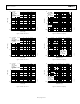
PIN CONFIGURATIONS AND FUNCTION DESCRIPTIONS
Figure 2. 8-Lead SOIC_N Pin Configuration (R-8) Figure 3. 8-Lead LFCSP Pin Configuration (CP-8-13)
Table 6. Pin Function Descriptions
Pin No. Mnemonic Description
1 SHUTDOWN Shutdown Enable.
2 BYPASS Bypass Capacitor.
3 IN+ Noninverting Input.
4 IN− Inverting Input.
5 V
OUT
A Output A.
6 V+ Positive Supply.
7 V− Negative Supply.
8 V
OUT
B Output B.
EPAD Exposed Pad. Connect the exposed pad to V−.
00358-002
SHUTDOWN
1
BYPASS
2
IN+
3
IN–
4
V
OUT
B
8
V–
7
V+
6
V
OUT
A
5
SSM2211
TOP VIEW
(Not to Scale)
SHUTDOWN
BYPASS
IN+
IN–
V–
V
OUT
B
V+
V
OUT
A
00358-003
3
4
1
2
6
5
8
7
TOP VIEW
(Not to Scale)
SSM2211
NOTES
1. CONNECT THE EXPOSED PAD TO V−.