
Datasheet


OP97
Rev. F | Page 13 of 16
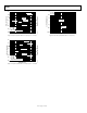
GUARDING AND SHIELDING
To maintain the extremely high input impedances of the OP97,
care must be taken in circuit board layout and manufacturing.
Board surfaces must be kept scrupulously clean and free of
moisture. Conformal coating is recommended to provide a
humidity barrier. Even a clean PCB can have 100 pA of leakage
currents between adjacent traces; therefore, use guard rings
around the inputs. Guard traces are operated at a voltage close
to that on the inputs, so that leakage currents are minimal. In
noninverting applications, connect the guard ring to the common-
mode voltage at the inverting input (Pin 2). In inverting appli-
cations, both inputs remain at ground, so that the guard trace
should be grounded. Make guard traces on both sides of the
circuit board.
High impedance circuitry is extremely susceptible to RF pickup,
line frequency hum, and radiated noise from switching power
supplies. Enclosing sensitive analog sections within grounded
shields is generally necessary to prevent excessive noise pickup.
Twisted-pair cable aid in rejection of line frequency hum.
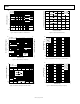
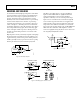
00299-035
V
OUT
OP97
2
3
6
I
O
I
O
30pF
AD7548
R
FB
DIGITAL
INPUTS
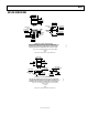
Figure 35. DAC Output Amplifier
The OP97 is an excellent choice as an output amplifier for
higher resolution CMOS DACs. Its tightly trimmed offset
voltage and minimal bias current result in virtually no
degradation of linearity, even over wide temperature ranges.
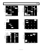
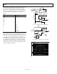
Figure 36 shows a versatile monitor circuit that can typically
sense current at any point between the ±15 V supplies. This
makes it ideal for sensing current in applications such as full
bridge drivers where bidirectional current is associated with
large common-mode voltage changes. The 114 dB CMRR of the
OP97 makes the contribution of the amplifier to common-
mode error negligible, leaving only the error due to the resistor
ratio inequality. Ideally, R2/R4 = R3/R5.
00299-036
V
OUT
R
L
I
L
2
3
6
7
4
R3
10kΩ
R2
10kΩ
R4
10kΩ
R5
10kΩ
R1
10kΩ
V
1
OP97
+15V
–15V
Figure 36. Current Monitor
00299-037
UNITY-GAIN FOLLOWE
R
INVERTING AMPLIFIER
OP97
2
3
6
OP97
2
3
6
NONINVERTING AMPLIFIE
R
OP97
2
3
6
PDIP
BOTTOM VIEW
81
Figure 37. Guard Ring Layout and Connections