
Inc. Bluetooth Headset User Manual

System Architecture
2-2 Bluetooth EZ-Extender Manual
System Architecture
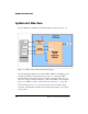
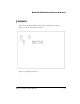
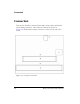
A block diagram of the Bluetooth EZ-Extender is shown in Figure 2-1.
The block diagram illustrates how the UART, SPORT, and USB ports are
interfaced the Bluetooth module and processor on a mating EZ-KIT
Lite/EZ-Board. The block diagram is a high-level diagram and does not
show the voltage translation circuitry or the clock buffers. The schematic
pages are available in “Bluetooth EZ-Extender Schematic” on page B-1.
The board supports 3.3, 2.5, and 1.8 volt I/O. The on-board voltage
translator automatically translates the motherboard signals to the correct
voltage levels.
Figure 2-1. Bluetooth EZ-Extender Block Diagram