
User manual
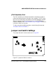


Jumper and Switch Settings
2-12 ADSP-BF538F EZ-KIT Lite Evaluation System Manual
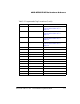
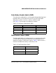
FCE Enable Switch (SW14)
The flash chip enable (FCE) switch (SW14) selects which ~AMS signals con-
nect to the internal flash memory. Since the internal memory is 1 MB,
only one ~AMS signal must be connected at a time. For each switch listed in
Table 2-7 that is turned ON, the size of available flash memory is reduced
by 1 MB.
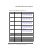
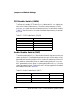
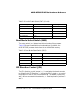
Audio Enable Switch (SW7)
The audio enable switch (SW7) disconnects the audio signals from the pro-
cessor (positions 1–5) and determines how the clock for the audio circuit
generates and connects (positions 6–8). Position 8 determines if the ADC
is in master or slave mode. When in master mode (position 8 is ON), the
ADC generates the clock. When in slave mode (position 8 is OFF), the pro-
cessor generates the clock. Positions 6 and 7 connect together the transmit
and receive clocks (see Table 2-8).
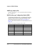
Table 2-7. FCE Enable Switch (SW14)
Processor Signal SW14 Switch Position (Default)
~AMS0 1 (OFF)
~AMS1 2 (OFF)
~AMS2 3 (OFF)
~AMS3 4 (OFF)
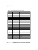
Table 2-8. Audio Enable Switch (SW7)
EZ-KIT Lite Signal SW7 Switch Position (Default) Processor Signal
DR0PRI 1 (ON) DR0PRI
RSCLK0 2 (ON) RSCLK0
RFS0 3 (ON) RFS0