
User manual

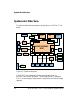

System Architecture
2-4 ADSP-BF538F EZ-KIT Lite Evaluation System Manual
SPORT0 Interface
SPORT0 connects to the audio circuit, SPORT0 connector (P6), and expan-
sion interface. The audio circuit uses the primary data transmit and
receive pins to input and output data from the audio input and outputs.
SPORT1 and SPORT2 of the processor connect to the SPORT connectors (P3
and
P4) and expansion interface.
The pinout of the SPORT interface and expansion interface connectors
can be found in “ADSP-BF538F EZ-KIT Lite Schematic” on page B-1.
SPI Interface
The serial peripheral interface (SPI) of the processor connects to the SPI
connectors (P1, P2, and P9) and expansion interface.
UART Interface
The UART interface of the processor connects to the UART connectors
(P12, P14, and P15) and expansion interface.
Programmable Flags
The processor has 53 general-purpose input/output (GPIO) signals spread
across four ports (PC, PD, PE, and PF). The pins are multi-functional and
depend on the processor setup. Table 2-1 shows how the programmable
flag pins are used on the EZ-KIT Lite.
Table 2-1. Programmable Flag Connections
Processor Pin Other Processor Function EZ-KIT Lite Function
PC0 CANTX UART0 CTS/CAN transmit
PC1 CANRX UART0 CTS/CAN receive