
User manual


Flash Memory
1-10 ADSP-BF538F EZ-KIT Lite Evaluation System Manual
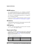
Automatic configuration of SDRAM is not optimized for any
SCLK fre-
quency. Table 1-3 shows optimized configuration for the SDRAM
registers using a 125 MHz and 133 MHz SCLK. Only the EBIU_SDRRC reg-
ister needs to be modified in the user code to achieve maximum
performance.
An example program is included in the EZ-KIT Lite installation directory
to demonstrate the SDRAM memory setup.
Flash Memory
The flash memory interface of the ADSP-BF538F EZ-KIT Lite can con-
nect to an external 4 MB (2M x 16-bits) ST Micro M29W320EB device
or the 1 MB internal flash memory. The size and connections of flash
memory are controlled by the flash address range switch (
SW6) and the flash
chip enable (FCE) switch (SW14). See “Flash Enable Switch (SW6)” on
page 2-11 and “FCE Enable Switch (SW14)” on page 2-12.
The default for the
SW6 switch is all positions ON, which allows the user to
have access to the full 4 MB of the external flash memory. The default for
the
SW14 switch is all positions OFF, which allows the user to have access to
the full 4 MB of the external flash memory. Each
~AMS signal accounts for
1 MB of flash memory. The amount of available flash memory decreases
as
~AMS signals are turned OFF.
Table 1-3. SDRAM Optimum Settings
Register SCLK = 133 MHz
(CCLK = 400 MHz)
SCLK = 125 MHz
(CCLK = 500 MHz)
EBIU_SDGCTL 0x0091 998D 0x0091 998D
EBIU_SDBCTL 0x0000 0025 0x0000 0025
EBIU_SDRRC 0x0000 0408 0x0000 03A0