
Datasheet


Table Of Contents
- FEATURES
- APPLICATIONS
- FUNCTIONAL BLOCK DIAGRAM
- TABLE OF CONTENTS
- SPECIFICATIONS
- ABSOLUTE MAXIMUM RATINGS
- PIN CONFIGURATION AND FUNCTION DESCRIPTIONS
- GENERAL DESCRIPTION
- TYPICAL PERFORMANCE CHARACTERISTICS
- FEATURES
- COLOR BAR GENERATION
- SQUARE PIXEL MODE
- COLOR SIGNAL CONTROL
- BURST SIGNAL CONTROL
- NTSC PEDESTAL CONTROL
- PIXEL TIMING DESCRIPTION
- SUBCARRIER RESET
- REAL-TIME CONTROL
- Video Timing Description
- Vertical Blanking Data Insertion
- Mode 0 (CCIR-656): Slave Option
- Mode 0 (CCIR-656): Master Option
- Mode 1: Slave Option HSYNC, BLANK, FIELD
- Mode 1: Master Option HSYNC, BLANK, FIELD
- Mode 2: Slave Option HSYNC, VSYNC, BLANK
- Mode 2: Master Option HSYNC, VSYNC, BLANK
- Mode 3: Master/Slave Option HSYNC, BLANK, FIELD
- POWER-ON RESET
- SCH PHASE MODE
- MPU PORT DESCRIPTION
- REGISTER ACCESSES
- REGISTER PROGRAMMING
- SUBADDRESS REGISTER (SR7–SR0)
- REGISTER SELECT (SR5–SR0)
- MODE REGISTER 1 (MR1)
- MODE REGISTER 2 (MR2)
- MODE REGISTER 3 (MR3)
- MODE REGISTER 4 (MR4)
- TIMING MODE REGISTER 0 (TR0)
- TIMING MODE REGISTER 1 (TR1)
- SUBCARRIER FREQUENCY REGISTERS 3–0
- SUBCARRIER PHASE REGISTER
- CLOSED CAPTIONING EVEN FIELD DATA REGISTERS 1–0
- CLOSED CAPTIONING ODD FIELD DATA REGISTERS 1–0
- NTSC PEDESTAL/PAL TELETEXT CONTROL REGISTERS 3–0
- TELETEXT REQUEST CONTROL REGISTER (TC07)
- CGMS_WSS REGISTER 0 (C/W0)
- CGMS_WSS REGISTER 1 (C/W1)
- CGMS_WSS REGISTER 2 (C/W2)
- APPENDIX 1—BOARD DESIGN AND LAYOUT CONSIDERATIONS
- APPENDIX 2—CLOSED CAPTIONING
- APPENDIX 3—COPY GENERATION MANAGEMENT SYSTEM (CGMS)
- APPENDIX 4—WIDE SCREEN SIGNALING (WSS)
- APPENDIX 5—TELETEXT
- APPENDIX 6—WAVEFORMS
- APPENDIX 7—OPTIONAL OUTPUT FILTER
- APPENDIX 8—RECOMMENDED REGISTER VALUES
- OUTLINE DIMENSIONS
ADV7174/ADV7179
Rev. B | Page 5 of 52
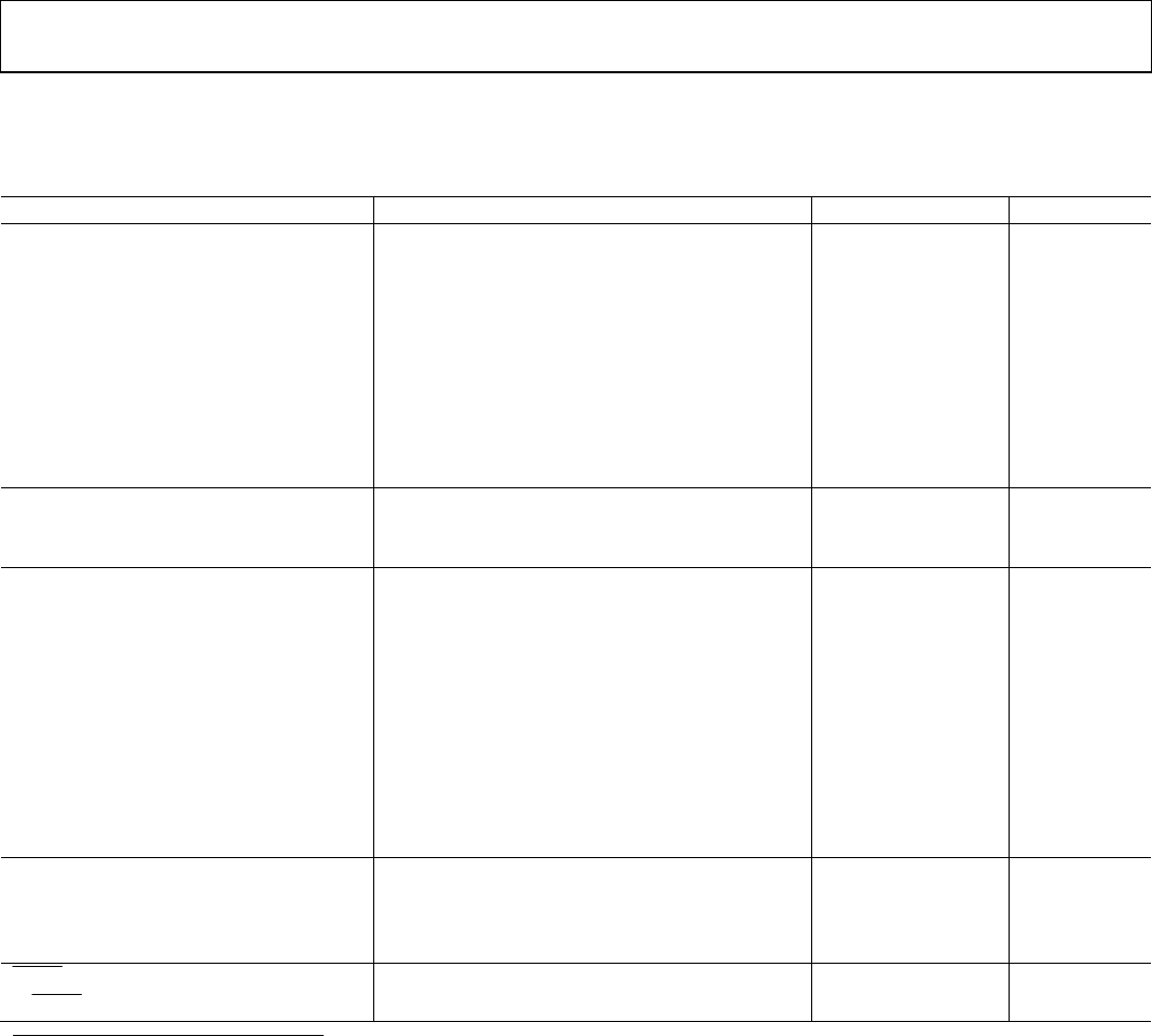
2.8 V TIMING SPECIFICATIONS
V
AA
= 2.8 V, V
REF
= 1.235 V, R
SET
= 150 Ω. All specifications T
MIN
to T
MAX
1
, unless otherwise noted.
Table 2.
Parameter Conditions
1
Min Typ Max Unit
MPU PORT
2, 3
SCLOCK Frequency 0 400 kHz
SCLOCK High Pulse Width, t
1
0.6 μs
SCLOCK Low Pulse Width, t
2
1.3 μs
Hold Time (Start Condition), t
3
After this period the first clock is generated 0.6 μs
Setup Time (Start Condition), t
4
Relevant for repeated start condition 0.6 μs
Data Setup Time, t
5
100 ns
SDATA, SCLOCK Rise Time, t
6
300 ns
SDATA, SCLOCK Fall Time, t
7
300 ns
Setup Time (Stop Condition), t
8
0.6 μs
ANALOG OUTPUTS
3, 4
Analog Output Delay 7 ns
DAC Analog Output Skew 0 ns
CLOCK CONTROL AND PIXEL PORT
4, 5
f
CLOCK
27 MHz
Clock High Time, t
9
8 ns
Clock Low Time, t
10
8 ns
Data Setup Time, t
11
3.5 ns
Data Hold Time, t
12
4 ns
Control Setup Time, t
11
4 ns
Control Hold Time, t
12
3 ns
Digital Output Access Time, t
13
12 ns
Digital Output Hold Time, t
1
4
8 ns
Pipeline Delay, t
PD
5
48 Clock Cycles
TELETEXT
3, 4, 6
Digital Output Access Time, t
16
23 ns
Data Setup Time, t
17
2 ns
Data Hold Time, t
18
6 ns
RESET
CONTROL
,
3 4
RESET
Low Time
6 ns
1
Temperature range T
MIN
to T
MAX
: –20°C to +85°C.
2
TTL input values are 0 V to 2.8 V, with input rise/fall times −3 ns, measured between the 10% and 90% points. Timing reference points at 50% for inputs and outputs.
Analog output load –10 pF.
3
Guaranteed by characterization.
4
Output delay measured from the 50% point of the rising edge of CLOCK to the 50% point of full-scale transition.
5
See Figure 60.
6
Teletext Port consists of the following:
Teletext Output: TTXREQ
Teletext Input: TTX