
Datasheet


Table Of Contents
- FEATURES
- APPLICATIONS
- FUNCTIONAL BLOCK DIAGRAM
- TABLE OF CONTENTS
- SPECIFICATIONS
- ABSOLUTE MAXIMUM RATINGS
- PIN CONFIGURATION AND FUNCTION DESCRIPTIONS
- GENERAL DESCRIPTION
- TYPICAL PERFORMANCE CHARACTERISTICS
- FEATURES
- COLOR BAR GENERATION
- SQUARE PIXEL MODE
- COLOR SIGNAL CONTROL
- BURST SIGNAL CONTROL
- NTSC PEDESTAL CONTROL
- PIXEL TIMING DESCRIPTION
- SUBCARRIER RESET
- REAL-TIME CONTROL
- Video Timing Description
- Vertical Blanking Data Insertion
- Mode 0 (CCIR-656): Slave Option
- Mode 0 (CCIR-656): Master Option
- Mode 1: Slave Option HSYNC, BLANK, FIELD
- Mode 1: Master Option HSYNC, BLANK, FIELD
- Mode 2: Slave Option HSYNC, VSYNC, BLANK
- Mode 2: Master Option HSYNC, VSYNC, BLANK
- Mode 3: Master/Slave Option HSYNC, BLANK, FIELD
- POWER-ON RESET
- SCH PHASE MODE
- MPU PORT DESCRIPTION
- REGISTER ACCESSES
- REGISTER PROGRAMMING
- SUBADDRESS REGISTER (SR7–SR0)
- REGISTER SELECT (SR5–SR0)
- MODE REGISTER 1 (MR1)
- MODE REGISTER 2 (MR2)
- MODE REGISTER 3 (MR3)
- MODE REGISTER 4 (MR4)
- TIMING MODE REGISTER 0 (TR0)
- TIMING MODE REGISTER 1 (TR1)
- SUBCARRIER FREQUENCY REGISTERS 3–0
- SUBCARRIER PHASE REGISTER
- CLOSED CAPTIONING EVEN FIELD DATA REGISTERS 1–0
- CLOSED CAPTIONING ODD FIELD DATA REGISTERS 1–0
- NTSC PEDESTAL/PAL TELETEXT CONTROL REGISTERS 3–0
- TELETEXT REQUEST CONTROL REGISTER (TC07)
- CGMS_WSS REGISTER 0 (C/W0)
- CGMS_WSS REGISTER 1 (C/W1)
- CGMS_WSS REGISTER 2 (C/W2)
- APPENDIX 1—BOARD DESIGN AND LAYOUT CONSIDERATIONS
- APPENDIX 2—CLOSED CAPTIONING
- APPENDIX 3—COPY GENERATION MANAGEMENT SYSTEM (CGMS)
- APPENDIX 4—WIDE SCREEN SIGNALING (WSS)
- APPENDIX 5—TELETEXT
- APPENDIX 6—WAVEFORMS
- APPENDIX 7—OPTIONAL OUTPUT FILTER
- APPENDIX 8—RECOMMENDED REGISTER VALUES
- OUTLINE DIMENSIONS
ADV7174/ADV7179
Rev. B | Page 49 of 52
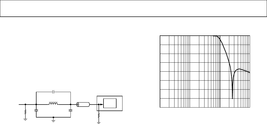
APPENDIX 7—OPTIONAL OUTPUT FILTER
If an output filter is required for the CVBS, Y, UV, chroma, and
RGB outputs of the ADV7174/ADV7179, the filter shown in
Figure 79 can be used. Plots of the filter characteristics are
shown in Figure 80. An output filter is not required if the
outputs of the ADV7174/ADV7179 are connected to most
analog monitors or analog TVs. However, if the output signals
are applied to a system where sampling is used (e.g., digital
TVs), then a filter is required to prevent aliasing.
1.8μH
75Ω
270pF
22pF
DISPLAY DEVICE
Z
0
= 75Ω
330pF
FILTER I/P
75Ω
02980-A-078
Figure 79. Output Filter
FREQUENCY (Hz)
0
80
100k
MAGNITUDE (dB)
70
60
50
40
30
20
10
1M
10M 100M
02980-A-079
Figure 80. Output Filter Plot