
Datasheet


Table Of Contents
- FEATURES
- APPLICATIONS
- FUNCTIONAL BLOCK DIAGRAM
- TABLE OF CONTENTS
- SPECIFICATIONS
- ABSOLUTE MAXIMUM RATINGS
- PIN CONFIGURATION AND FUNCTION DESCRIPTIONS
- GENERAL DESCRIPTION
- TYPICAL PERFORMANCE CHARACTERISTICS
- FEATURES
- COLOR BAR GENERATION
- SQUARE PIXEL MODE
- COLOR SIGNAL CONTROL
- BURST SIGNAL CONTROL
- NTSC PEDESTAL CONTROL
- PIXEL TIMING DESCRIPTION
- SUBCARRIER RESET
- REAL-TIME CONTROL
- Video Timing Description
- Vertical Blanking Data Insertion
- Mode 0 (CCIR-656): Slave Option
- Mode 0 (CCIR-656): Master Option
- Mode 1: Slave Option HSYNC, BLANK, FIELD
- Mode 1: Master Option HSYNC, BLANK, FIELD
- Mode 2: Slave Option HSYNC, VSYNC, BLANK
- Mode 2: Master Option HSYNC, VSYNC, BLANK
- Mode 3: Master/Slave Option HSYNC, BLANK, FIELD
- POWER-ON RESET
- SCH PHASE MODE
- MPU PORT DESCRIPTION
- REGISTER ACCESSES
- REGISTER PROGRAMMING
- SUBADDRESS REGISTER (SR7–SR0)
- REGISTER SELECT (SR5–SR0)
- MODE REGISTER 1 (MR1)
- MODE REGISTER 2 (MR2)
- MODE REGISTER 3 (MR3)
- MODE REGISTER 4 (MR4)
- TIMING MODE REGISTER 0 (TR0)
- TIMING MODE REGISTER 1 (TR1)
- SUBCARRIER FREQUENCY REGISTERS 3–0
- SUBCARRIER PHASE REGISTER
- CLOSED CAPTIONING EVEN FIELD DATA REGISTERS 1–0
- CLOSED CAPTIONING ODD FIELD DATA REGISTERS 1–0
- NTSC PEDESTAL/PAL TELETEXT CONTROL REGISTERS 3–0
- TELETEXT REQUEST CONTROL REGISTER (TC07)
- CGMS_WSS REGISTER 0 (C/W0)
- CGMS_WSS REGISTER 1 (C/W1)
- CGMS_WSS REGISTER 2 (C/W2)
- APPENDIX 1—BOARD DESIGN AND LAYOUT CONSIDERATIONS
- APPENDIX 2—CLOSED CAPTIONING
- APPENDIX 3—COPY GENERATION MANAGEMENT SYSTEM (CGMS)
- APPENDIX 4—WIDE SCREEN SIGNALING (WSS)
- APPENDIX 5—TELETEXT
- APPENDIX 6—WAVEFORMS
- APPENDIX 7—OPTIONAL OUTPUT FILTER
- APPENDIX 8—RECOMMENDED REGISTER VALUES
- OUTLINE DIMENSIONS
ADV7174/ADV7179
Rev. B | Page 32 of 52
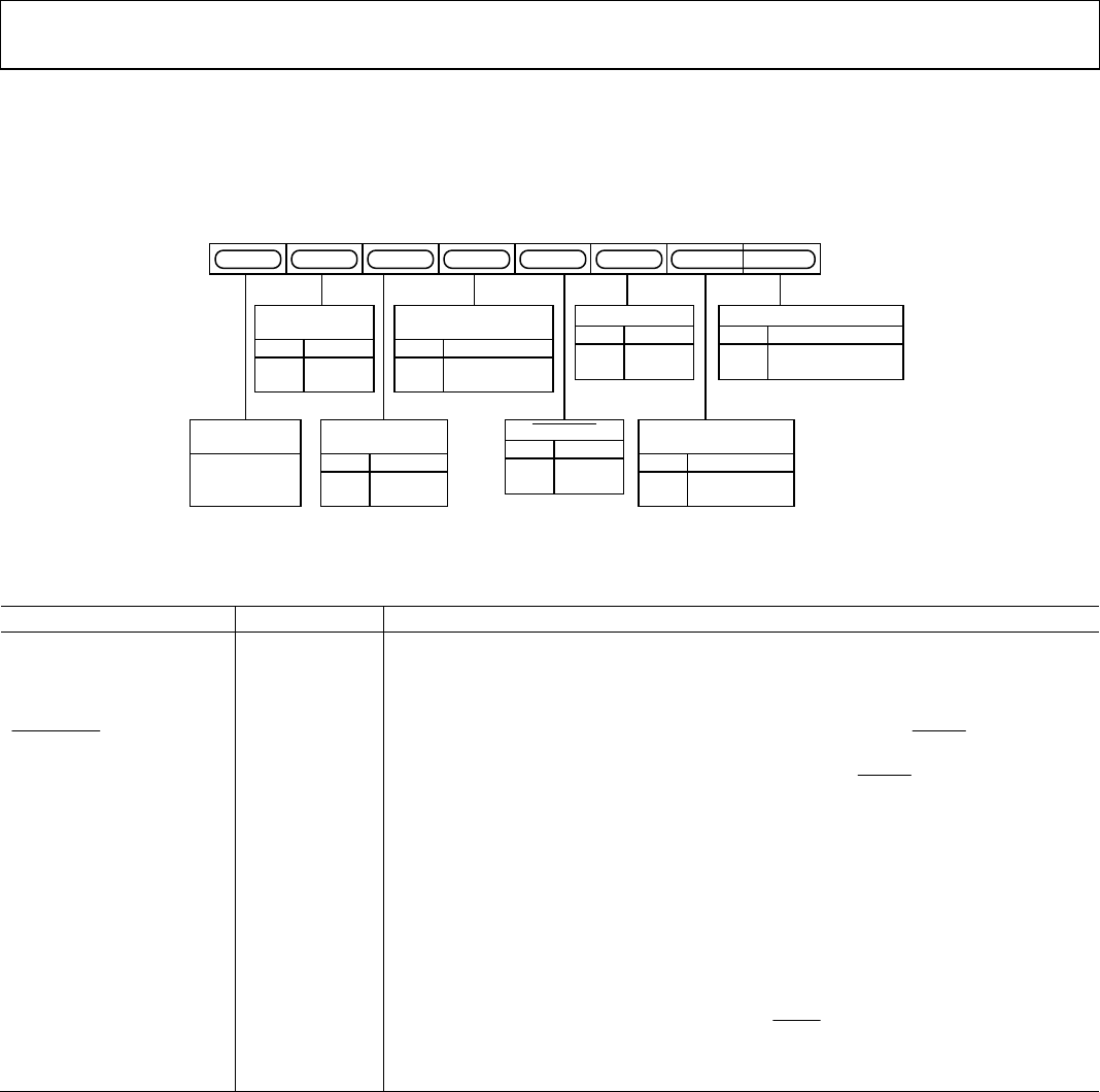
MODE REGISTER 4 (MR4)
Bits: MR47–MR40
Address: SR4–SR0 = 04H
Mode Register 4 is an 8-bit-wide register. Figure 42 shows the various operations under the control of Mode Register 4.
MR41
MR40
MR47
MR42MR44 MR43MR45MR46
OUTPUT SELECT
0 YC OUTPUT
1 RGB/YPbPr OUTPUT
MR40
RGB SYNC
0 DISABLE
1 ENABLE
MR42
PEDESTAL
CONTROL
0 PEDESTAL OFF
1 PEDESTAL ON
MR44
SLEEP MODE
CONTROL
0 DISABLE
1 ENABLE
MR46
ACTIVE VIDEO
FILTER CONTROL
0 DISABLE
1 ENABLE
MR45
MR47
(0)
ZERO SHOULD
BE WRITTEN TO
THIS BIT
VSYNC_3H
0 DISABLE
1 ENABLE
MR43
RGB/YUV
CONTROL
0 RGB OUTPUT
1 YPbPr OUTPUT
MR41
02980-A-041
Figure 42. Mode Register 4
Table 14. MR4 Bit Description
Bit Name Bit No. Description
Output Select MR40 This bit specifies if the part is in composite video or RGB/YPbPr mode.
RGB/YPbPr Control MR41 This bit enables the output from the RGB DACs to be set to YPbPr output video standard.
RGB Sync MR42
This bit is used to set up the RGB outputs with the sync information encoded on all RGB
outputs.
VSYNC_3H
MR43
When this bit is enabled (1) in slave mode, it is possible to drive the VSYNC active low
input for 2.5 lines in PAL mode and three lines in NTSC mode. When this bit is enabled in
master mode, the ADV7174/ADV7179 outputs an active low VSYNC signal for three lines
in NTSC mode and 2.5 lines in PAL mode.
Pedestal Control MR44
This bit specifies whether a pedestal is to be generated on the NTSC composite video
signal. This bit is invalid if the ADV7174/ ADV7179 is configured in PAL mode.
Active Video Filter Control MR45
This bit controls the filter mode applied outside the active video portion of the line. This
filter ensures that the sync rise and fall times are always on spec regardless of which luma
filter is selected. A Logic 1 enables this mode.
Sleep Mode Control MR46
When this bit is set (1), sleep mode is enabled. With this mode enabled, the
ADV7174/ADV7179 power consumption is reduced to typically 200 nA. The I
2
C registers
can be written to and read from when the ADV7174/ADV7179 is in sleep mode. If MR46 is
set to a (0) when the device is in sleep mode, the ADV7174/ADV7179 comes out of sleep
mode and resumes normal operation. Also, if the RESET
signal is applied during sleep
mode, the ADV7174/ADV7179 comes out of sleep mode and resumes normal operation.
Reserved MR47 A Logic 0 should be written to this bit.