
Datasheet


Table Of Contents
- FEATURES
- APPLICATIONS
- FUNCTIONAL BLOCK DIAGRAM
- TABLE OF CONTENTS
- SPECIFICATIONS
- ABSOLUTE MAXIMUM RATINGS
- PIN CONFIGURATION AND FUNCTION DESCRIPTIONS
- GENERAL DESCRIPTION
- TYPICAL PERFORMANCE CHARACTERISTICS
- FEATURES
- COLOR BAR GENERATION
- SQUARE PIXEL MODE
- COLOR SIGNAL CONTROL
- BURST SIGNAL CONTROL
- NTSC PEDESTAL CONTROL
- PIXEL TIMING DESCRIPTION
- SUBCARRIER RESET
- REAL-TIME CONTROL
- Video Timing Description
- Vertical Blanking Data Insertion
- Mode 0 (CCIR-656): Slave Option
- Mode 0 (CCIR-656): Master Option
- Mode 1: Slave Option HSYNC, BLANK, FIELD
- Mode 1: Master Option HSYNC, BLANK, FIELD
- Mode 2: Slave Option HSYNC, VSYNC, BLANK
- Mode 2: Master Option HSYNC, VSYNC, BLANK
- Mode 3: Master/Slave Option HSYNC, BLANK, FIELD
- POWER-ON RESET
- SCH PHASE MODE
- MPU PORT DESCRIPTION
- REGISTER ACCESSES
- REGISTER PROGRAMMING
- SUBADDRESS REGISTER (SR7–SR0)
- REGISTER SELECT (SR5–SR0)
- MODE REGISTER 1 (MR1)
- MODE REGISTER 2 (MR2)
- MODE REGISTER 3 (MR3)
- MODE REGISTER 4 (MR4)
- TIMING MODE REGISTER 0 (TR0)
- TIMING MODE REGISTER 1 (TR1)
- SUBCARRIER FREQUENCY REGISTERS 3–0
- SUBCARRIER PHASE REGISTER
- CLOSED CAPTIONING EVEN FIELD DATA REGISTERS 1–0
- CLOSED CAPTIONING ODD FIELD DATA REGISTERS 1–0
- NTSC PEDESTAL/PAL TELETEXT CONTROL REGISTERS 3–0
- TELETEXT REQUEST CONTROL REGISTER (TC07)
- CGMS_WSS REGISTER 0 (C/W0)
- CGMS_WSS REGISTER 1 (C/W1)
- CGMS_WSS REGISTER 2 (C/W2)
- APPENDIX 1—BOARD DESIGN AND LAYOUT CONSIDERATIONS
- APPENDIX 2—CLOSED CAPTIONING
- APPENDIX 3—COPY GENERATION MANAGEMENT SYSTEM (CGMS)
- APPENDIX 4—WIDE SCREEN SIGNALING (WSS)
- APPENDIX 5—TELETEXT
- APPENDIX 6—WAVEFORMS
- APPENDIX 7—OPTIONAL OUTPUT FILTER
- APPENDIX 8—RECOMMENDED REGISTER VALUES
- OUTLINE DIMENSIONS
ADV7174/ADV7179
Rev. B | Page 29 of 52
MODE REGISTER 1 (MR1)
Bits: MR17–MR10
Address: SR4–SR0 = 01H
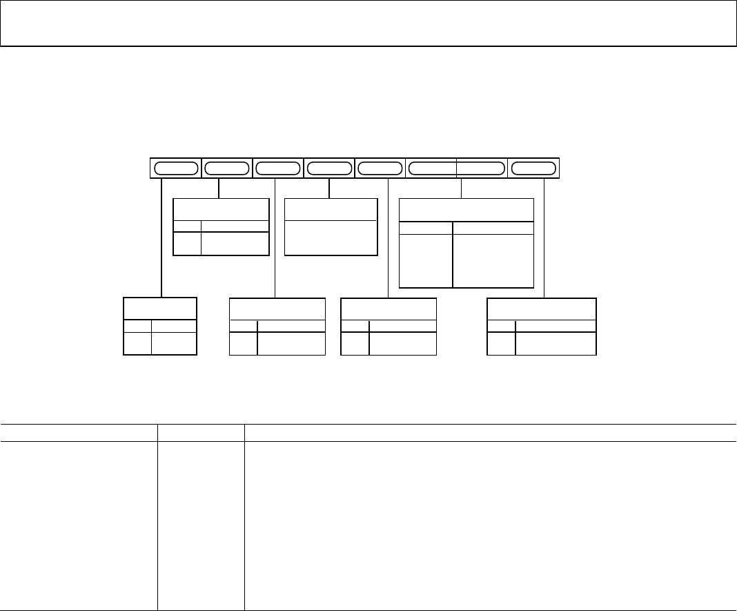
Figure 39 shows the various operations under the control of Mode Register 1. This register can be read from as well as written to.
MR11 MR10MR17 MR12MR13MR15MR16 MR14
CLOSED CAPTIONING
FIELD SELECTION
0 NO DATA OUT
0 ODD FIELD ONLY
1 EVEN FIELD ONLY
1
0
1
0
1 DATA OUT
(BOTH FIELDS)
MR12
MR11
DAC A
CONTROL
0 NORMAL
1 POWER-DOWN
MR16
RESERVED
DAC C
CONTROL
MR13
DAC B
CONTROL
MR15
INTERLACE
CONTROL
0 INTERLACED
1 NONINTERLACED
MR10
COLOR BAR
CONTROL
0 DISABLE
1 ENABLE
MR17
0 NORMAL
1 POWER-DOWN
0 NORMAL
1 POWER-DOWN
1 SHOULD BE
WRITTEN TO
THIS BIT
02980-A-039
Figure 39. Mode Register 1
Table 10. MR1 Bit Description
Bit Name Bit No. Description
Interlace Control MR10
This bit is used to set up the output to interlaced or noninterlaced mode. Power-down mode
is relevant only when the part is in composite video mode.
Closed Captioning Field
Selection
MR12–MR11
These bits control the fields on which closed captioning data is displayed; closed captioning
information can be displayed on an odd field, even field, or both fields.
DAC Control
MR16–MR15
and MR13
These bits can be used to power down the DACs. Power-down can be used to reduce the
power consumption of the ADV7174/ADV7179 if any of the DACs are not required in the
application.
Reserved MR14
A Logic 1 must be written to this register.
Color Bar Control MR17
This bit can be used to generate and output an internal color bar test pattern. The color bar
configuration is 100/7.5/75/7.5 for NTSC and 100/0/75/0 for PAL. It is important to note that
when color bars are enabled, the ADV7174/ADV7179 is configured in a master timing mode.