
Datasheet


ADG741/ADG742
Rev. A | Page 6 of 12
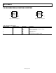
PIN CONFIGURATIONS AND FUNCTION DESCRIPTIONS
02076-002
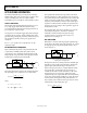
NC = NO CONNECT
D
1
S
2
GND
3
V
DD
6
NC
5
IN
4
ADG741/
ADG742
TOP VIEW
(Not to Scale)
Figure 3. 6-Lead Pin Configuration
02076-018
D
1
GND
3
S
2
V
DD
5
IN
4
ADG741/
ADG742
TOP VIEW
(Not to Scale)
Figure 4. 5-Lead Pin Configuration
Table 5. Pin Function Descriptions
Pin No. (6-Lead) Pin No. (5-Lead) Mnemonic Description
1 1 D Drain Terminal. May be an input or output.
2 2 S Source Terminal. May be an input or output.
3 3 GND Ground (0 V) Reference.
4 4 IN Logic Control Input.
5 - NC No Connect.
6 5 V
DD
Most Positive Power Supply Potential.