
Datasheet
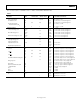


ADG633
Rev. A | Page 5 of 16
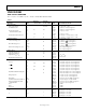
V
DD
= 2.7 V to 3.6 V, V
SS
= 0 V, GND = 0 V, T
A
= −40°C to +125°C, unless otherwise noted.
Table 3.
B Version Y Version
Parameter +25°C −40°C to +85°C −40°C to +125°C Unit Test Conditions/Comments
ANALOG SWITCH
Analog Signal Range 0 to V
DD
V V
DD
= 2.7 V, V
SS
= 0 V
On Resistance, R
ON
185 Ω typ V
S
= 0 V to 2.7 V, I
S
= 0.1 mA; see Figure 20
300 350 400 Ω max V
S
= 0 V to 2.7 V, I
S
= 0.1 mA; see Figure 20
On-Resistance Match
Between Channels, ΔR
ON
2 Ω typ V
S
= +1.5 V, I
S
= 0.1 mA
4.5 6 7 Ω max V
S
= +1.5 V, I
S
= 0.1 mA
LEAKAGE CURRENTS V
DD
= 3.3 V
Source Off Leakage, I
S(OFF)
±0.005 nA typ V
S
= 1 V/3 V, V
D
= 3 V/1 V; see Figure 21
±0.2 ±5 nA max V
S
= 1 V/3 V, V
D
= 3 V/1 V; see Figure 21
Drain Off Leakage, I
D(OFF)
±0.005 nA typ V
S
= 1 V/3 V, V
D
= 3 V/1 V; see Figure 22
±0.2 ±5 nA max V
S
= 1 V/3 V, V
D
= 3 V/1 V; see Figure 22
Channel On Leakage, I
D(ON)
, I
S(ON)
±0.005 nA typ V
S
= V
D
= 1 V or 3 V; see Figure 23
±0.2 ±5 nA max V
S
= V
D
= 1 V or 3 V; see Figure 23
DIGITAL INPUTS
Input High Voltage, V
INH
2.0 V min
Input Low Voltage, V
INL
0.5 V max
Input Current, I
INL
or I
INH
0.005 μA typ V
IN
= V
INL
or V
INH
±1 μA max V
IN
= V
INL
or V
INH
Digital Input Capacitance, C
IN
2 pF typ
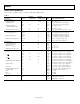
DYNAMIC CHARACTERISTICS
1
t
TRANSITION
170 ns typ R
L
= 300 Ω, C
L
= 35 pF, V
S
= 1.5 V; see Figure 24
300 370 400 ns max R
L
= 300 Ω, C
L
= 35 pF, V
S
= 1.5 V; see Figure 24
t
ON
(
EN
)
200 ns typ R
L
= 300 Ω, C
L
= 35 pF, V
S
= 1.5 V; see Figure 26
310 380 420 ns max R
L
= 300 Ω, C
L
= 35 pF, V
S
= 1.5 V; see Figure 26
t
OFF
(
EN
)
30 ns typ R
L
= 300 Ω, C
L
= 35 pF, V
S
= 1.5 V; see Figure 26
40 55 75 ns max R
L
= 300 Ω, C
L
= 35 pF, V
S
= 1.5 V; see Figure 26
Break-Before-Make Time Delay, t
BBM
180 ns typ R
L
= 300 Ω, C
L
= 35 pF, V
S1
= V
S2
= 1.5 V; see Figure 25
10 ns min R
L
= 300 Ω, C
L
= 35 pF, V
S1
= V
S2
= 1.5 V; see Figure 25
Charge Injection 1 pC typ V
S
= 1.5 V, R
S
= 0 Ω, C
L
= 1 nF; see Figure 27
2 pC max V
S
= 1.5 V, R
S
= 0 Ω, C
L
= 1 nF; see Figure 27
Off Isolation −90 dB typ R
L
= 50 Ω, C
L
= 5 pF, f = 1 MHz; see Figure 28
Channel-to-Channel Crosstalk −90 dB typ R
L
= 50 Ω, C
L
= 5 pF, f = 1 MHz; see Figure 30
−3 dB Bandwidth 500 MHz typ R
L
= 50 Ω, C
L
= 5 pF; see Figure 29
C
S(OFF)
5 pF typ f = 1 MHz
C
D(OFF)
8 pF typ f = 1 MHz
C
D(ON)
, C
S(ON)
12 pF typ f = 1 MHz
POWER REQUIREMENTS V
DD
= 3.3 V
I
DD
0.01 μA typ Digital inputs = 0 V or 3.3 V
1 μA max Digital inputs = 0 V or 3.3 V
1
Guaranteed by design; not subject to production test.