
Datasheet


Data Sheet ADF4153A
Rev. A | Page 17 of 24
INITIALIZATION SEQUENCE
The following initialization sequence should be followed upon
powering up the part:
1. Write all zeros to the noise and spur register. This ensures
that all test modes are cleared.
2. Write again to the noise and spur register, this time
selecting which noise and spur mode is required. For
example, writing Hexadecimal 0003C7 to the part selects
lowest noise mode.
3. Enable the counter reset in the control register by writing a
1 to DB2; also select the required settings in the control
register. If using the phase resync function, set the resync
bits to the required settings.
4. Load the R divider register (with load control DB23
set to 0).
5. Load the N divider register.
6. Disable the counter reset by writing a 0 to DB2 in the
control register.
The part now locks to the set frequency.
If using the phase resync function, an extra step is needed after
Step 3. This involves loading the R divider register with load
control = 1 and the required delay interval in place of the MOD
value. The previous sequence can then be followed, ensuring
that in Step 4 the value of MOD is written to the R divider
register with load control = 0.
See the Spur Consistency and Phase Resync sections for more
information on the phase resync feature.
RF SYNTHESIZER: A WORKED EXAMPLE
The following equation governs how the synthesizer is
programmed:
RF
OUT
= [INT + (FRAC/MOD)] × [F
PFD
] (3)
where:
RF
OUT
is the RF frequency output.
INT is the integer division factor.
FRAC is the fractionality.
MOD is the modulus.
The PFD frequency is given by:
F
PFD
= [REF
IN
× (1 + D)/R] (4)
where:
REF
IN
is the reference frequency input.
D is the RF REF
IN
doubler bit.
R is the RF reference division factor.
For example, in a GSM 1800 system, where 1.8 GHz RF
frequency output (RF
OUT
) is required, a 13 MHz reference
frequency input (REF
IN
) is available and a 200 kHz channel
resolution (f
RES
) is required on the RF output. With REF
IN
doubler (D) set to 0 and reference division (R) set to 1, from
Equation 4:
F
PFD
= [13 MHz × (1 + 0)/1] = 13 MHz (5)
MOD = F
PFD
/f
RES
MOD = 13 MHz/200 kHz = 65
1.8 G = 13 MHz × (INT + FRAC/65)
where INT = 138; FRAC = 30 (6)
MODULUS
The choice of modulus (MOD) depends on the PFD frequency
(which depends on the available reference signal REF
IN
) and
the channel resolution (f
RES
) required at the RF output. For
example, a GSM system with 13 MHz REF
IN
sets the modulus to
65. This means that the RF output resolution (f
RES
) is the 200 kHz
(13 MHz/65) necessary for GSM. With dither off, the fractional
spur interval depends on the modulus values chosen. See Table 6
for more information.
REFERENCE DOUBLER AND REFERENCE DIVIDER
The reference doubler on-chip allows the input reference signal
to be doubled. This is useful for increasing the PFD comparison
frequency. Making the PFD frequency higher improves the
noise performance of the system. Doubling the PFD frequency
usually improves noise performance by 3 dB. It is important to
note that the PFD cannot be operated above specified limits due
to a limitation in the speed of the Σ-Δ circuit of the N divider.
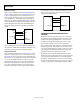
12-BIT PROGRAMMABLE MODULUS
Unlike most other fractional-N PLLs, the ADF4153A lets the
user program the modulus over a 12-bit range. This means that
the user can set up the part in many different configurations for
the application, when combined with the reference doubler and
the 4-bit R counter.
The following is an example of an application that requires
1.75 GHz RF and 200 kHz channel step resolution. The system
has a 13 MHz reference signal.
One possible setup is feeding the 13 MHz directly to the PFD
and programming the modulus to divide by 65. This results in
the required 200 kHz resolution.
Another possible setup is using the reference doubler to create
26 MHz from the 13 MHz input signal. This 26 MHz is then fed
into the PFD. The modulus is now programmed to divide by
130. This also results in 200 kHz resolution and offers superior
phase noise performance over the previous setup.