
Datasheet
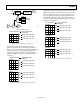


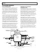
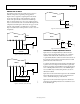
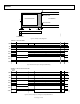

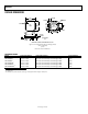


Table Of Contents
- FEATURES
- APPLICATIONS
- GENERAL DESCRIPTION
- FUNCTIONAL BLOCK DIAGRAM
- TABLE OF CONTENTS
- REVISION HISTORY
- SPECIFICATIONS
- ABSOLUTE MAXIMUM RATINGS
- PIN CONFIGURATION AND FUNCTION DESCRIPTIONS
- TERMINOLOGY
- EQUIVALENT INPUT/OUTPUT CIRCUITS
- TYPICAL PERFORMANCE CHARACTERISTICS
- SYSTEM OVERVIEW
- SERIAL INTERFACE TIMING
- COMPLETE REGISTER LISTING
- PRECISION TIMING HIGH SPEED TIMING GENERATION
- HORIZONTAL CLAMPING AND BLANKING
- GENERATING SPECIAL HBLK PATTERNS
- POWER-UP PROCEDURE
- ANALOG FRONT END DESCRIPTION AND OPERATION
- APPLICATIONS INFORMATION
- OUTLINE DIMENSIONS
AD9949
Rev. B | Page 31 of 36
DRIVING THE CLI INPUT
The AD9949’s master clock input (CLI) may be used in two
different configurations, depending on the application.
Figure 41 shows a typical dc-coupled input from the master
clock source. When the dc-coupled technique is used, the
master clock signal should be at standard 3 V CMOS logic
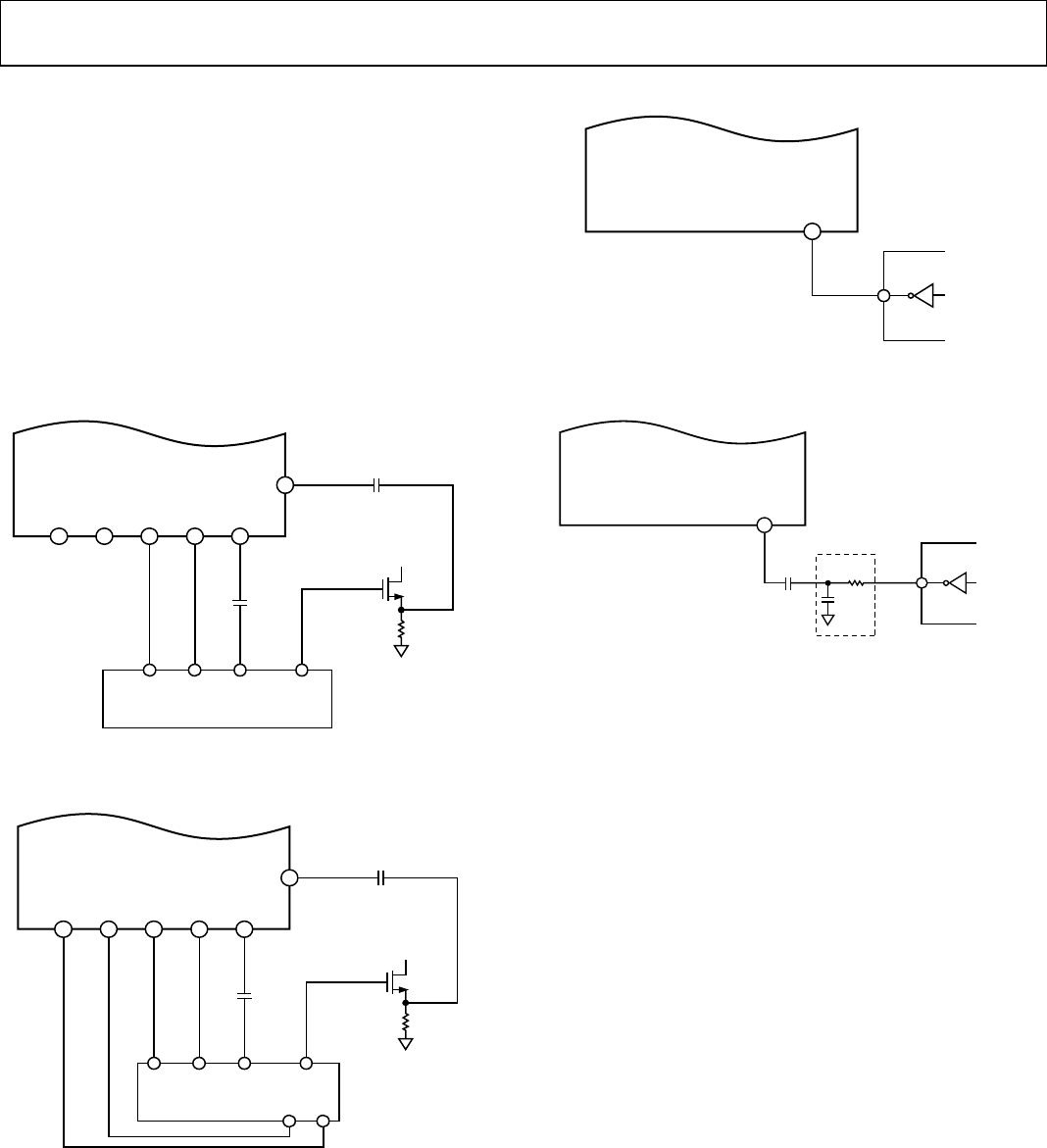
levels. As shown in Figure 42, a 1000 pF ac-coupling capacitor
may be used between the clock source and the CLI input. In this
configuration, the CLI input is self-biased to the proper dc volt-
age level of approximately 1.4 V. When the ac-coupled tech-
nique is used, the master clock signal can be as low as ±500 mV
in amplitude.
CCD IMAGER
SIGNAL
OUT
H2 RGH3 H4 H1
H2H1 RG
AD9949
CCDIN
03751-040
18 19 14 15 21
27
Figure 39. CCD Connections (2 H-Clock)
03751-041
CCD IMAGER
SIGNAL
OUT
H4 RGH1 H2 H3
H4
H2 H1
H3 RG
AD9949
CCDIN
14 15 18 19 21
27
Figure 40. CCD Connections (4 H-Clock)
03751-042
CLI
AD9949
25
ASIC
MASTER CLOCK
Figure 41. CLI Connection, DC-Coupled
LPF
1nF
03751-043
CLI
AD9949
25
ASIC
MASTER CLOCK
Figure 42. CLI Connection, AC-Coupled
HORIZONTAL TIMING SEQUENCE EXAMPLE
Figure 43 shows an example CCD layout. The horizontal
register contains 28 dummy pixels, which occur on each line
clocked from the CCD. In the vertical direction, there are
10 optical black (OB) lines at the front of the readout and two at
the back of the readout. The horizontal direction has four OB
pixels in the front and 48 in the back.
To configure the AD9949 horizontal signals for this CCD, three
sequences can be used. Figure 44 shows the first sequence that
should be used during vertical blanking. During this time, there
are no valid OB pixels from the sensor, so the CLPOB signal is
not used. PBLK may be enabled during this time, because no
valid data is available.
Figure 45 shows the recommended sequence for the vertical OB
interval. The clamp signals are used across the whole lines in
order to stabilize the clamp loop of the AD9949.
Figure 46 shows the recommended sequence for the effective
pixel readout. The 48 OB pixels at the end of each line are used
for the CLPOB signal.