
Analog Interface for Flat Panel Displays Specification Sheet


REV. 0
AD9883A
–11–
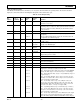
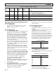
Table V. Recommended VCO Range and Charge Pump Current Settings for Standard Display Formats
Refresh Horizontal
Standard Resolution Rate Frequency Pixel Rate VCORNGE Current
VGA 640 × 480 60 Hz 31.5 kHz 25.175 MHz 00 101
72 Hz 37.7 kHz 31.500 MHz 00 110
75 Hz 37.5 kHz 31.500 MHz 00 110
85 Hz 43.3 kHz 36.000 MHz 00 110
SVGA 800 × 600 56 Hz 35.1 kHz 36.000 MHz 00 110
60 Hz 37.9 kHz 40.000 MHz 01 100
72 Hz 48.1 kHz 50.000 MHz 01 100
75 Hz 46.9 kHz 49.500 MHz 01 100
85 Hz 53.7 kHz 56.250 MHz 01 101
XGA 1024 × 768 60 Hz 48.4 kHz 65.000 MHz 01 110
70 Hz 56.5 kHz 75.000 MHz 10 100
75 Hz 60.0 kHz 78.750 MHz 10 100
80 Hz 64.0 kHz 85.500 MHz 10 100
85 Hz 68.3 kHz 94.500 MHz 10 100
SXGA 1280 × 1024 60 Hz 64.0 kHz 108.000 MHz 10 110
75 Hz 80.0 kHz 135.000 MHz 11 101
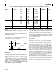
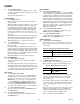
Timing
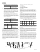
The following timing diagrams show the operation of the
AD9883A.
The Output Data Clock signal is created so that its rising edge
always occurs between data transitions, and can be used to latch
the output data externally.
There is a pipeline in the AD9883A, which must be flushed
before valid data becomes available. This means four data sets
are presented before valid data is available.
t
PER
t
CYCLE
t
SKEW
DATACK
DATA
HSOUT
Figure 7. Output Timing
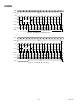
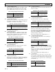
Hsync Timing
Horizontal Sync (Hsync) is processed in the AD9883A to elimi-
nate ambiguity in the timing of the leading edge with respect to
the phase-delayed pixel clock and data.
The Hsync input is used as a reference to generate the pixel
sampling clock. The sampling phase can be adjusted, with respect
to Hsync, through a full 360° in 32 steps via the Phase Adjust
register (to optimize the pixel sampling time). Display systems
use Hsync to align memory and display write cycles, so it is
important to have a stable timing relationship between Hsync
output (HSOUT) and data clock (DATACK).
Three things happen to Horizontal Sync in the AD9883A. First,
the polarity of Hsync input is determined and will thus have a
known output polarity. The known output polarity can be pro-
grammed either active high or active low (register 0EH, Bit 5).
Second, HSOUT is aligned with DATACK and data outputs.
Third, the duration of HSOUT (in pixel clocks) is set via regis-
ter 07H. HSOUT is the sync signal that should be used to drive
the rest of the display system.
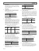
Coast Timing
In most computer systems, the Hsync signal is provided con-
tinuously on a dedicated wire. In these systems, the COAST
input and function are unnecessary, and should not be used and
the pin should be permanently connected to the inactive state.
In some systems, however, Hsync is disturbed during the
Vertical Sync period (Vsync). In some cases, Hsync pulses
disappear. In other systems, such as those that employ Compos-
ite Sync (Csync) signals or embedded Sync-on-Green (SOG),
Hsync includes equalization pulses or other distortions during
Vsync. To avoid upsetting the clock generator during Vsync,
it is important to ignore these distortions. If the pixel clock
PLL sees extraneous pulses, it will attempt to lock to this new
frequency, and will have changed frequency by the end of the
Vsync period. It will then take a few lines of correct Hsync tim-
ing to recover at the beginning of a new frame, resulting in a
“tearing” of the image at the top of the display.
The COAST input is provided to eliminate this problem. It is
an asynchronous input that disables the PLL input and allows
the clock to free-run at its then-current frequency. The PLL can
free-run for several lines without significant frequency drift.