
Datasheet

Quick Start Guide AD9739A-EBZ
Rev. A | Page 7 of 8
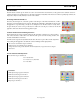
The status read back bits for the mu controller are as follows:
MU_LCK: Register
0x2A bit 0 (value of 1 means the controller is locked)
LST_LCK: Register 0x2A bit 1 (Value of 1 means the control lost lock)
In order to read back the present MU Delay and phase value, it is necessary to set the Read bit high and then
low before the value
s can be read back:
Read: Register 0x26 Bit 3
Mu Delay Readback: Register 0x28 bits 0
-7 and 0x27 bits 6,7
(Total of 9 bits in the read back the maximum Mu delay value is d432 or x1B0)
MUD_PH_Readback: Register 0x27 bits 0
-4 – Phase the controller locked to.
In order to use the Mu controller in manual mode the following bits are utilized:
Mu Controller Enable: Register 0x26 Bit 0 (Set to 0 to disable the controller)
MU_DEL_Manual: Register 0x28 bits 0
-7 and 0x27 bits 7,8. (Total of 9 bits
the maximum Mu
delay value is d432 or x1B0)
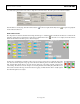
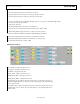
LVDS Receiver Controls
Figure 14
RCV_LOOP
- On (Register 0x10 bit 1 set to 1)
RCV_ENA
- On (Register 0x10 bit 0 set to 1)
LCKTHR
- 2 (Register 0x15 bits 0-4)
RVCR_GAIN
- 1 (Register 0x11 bit 0 set to 1)
FINE_DELAY_MID
- 7 (Register 0x11 bits 2-5)
FINE_DELAY_SKEW
- 2 (Register 0x13 bits 0-4)
Sample_Delay: Sets the midpoint where the controller begins to search Register 0x11 bits 6,7
Register 0x12 Optimal value is 166 which is the center of the delay
line. The maximum delay
value is d333 or x14D.
DCI_Delay: Must be equal to the Sample_delay. Register 0x13 bits 4
-7 Register 0x14 bits 0-5.
Optimal value is also 166 which is the center of the delay line. The maximum delay value is
d333 or x14D.