
Datasheet

Quick Start Guide AD9739A-EBZ
Rev. A | Page 6 of 8
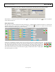
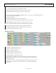
Mu Controller
Figure 13
Mu Controller Enable: Register 0x26 Bit 0 (Set to 1 to enable the controller)
Mu
Controller Gain: Register 0x26 Bits 1,2 (Optimal Setting is a Gain of 1)
MU Desired Phase
: Desired Phase Value for Phase to Voltage Converter to Optimize Mu Controller. The
optimal setting is negative 6 (max of 16) . Register 0x27 bits 0
-4
Slope: Slope
the mu contoller will lock onto Register 0x26 bit 6 (Optimal setting is Negative slope set bit to 0)
MU_DEL_Manual: Register 0x28 bits 0
-7 and 0x27 bits 6,7: Sets the point where the Mu Controller begins to
search. It is best to set it to the middle of th
e delay line . The maximum Mu delay is 432, so set these bits to
approximately 220.
Mode: Register: 0x26 Bits 4, 5 Sets the Mode in which the Controller searches:
0x00 – Search and Track (Optimal Setting)
0x01 – Track Only
0x10 – Search Only
0x11 – Invalid
Search Mode: 0x27
– Bits 5, 6 Sets the Mode in which the search for the optimal phase is performed
0x00 – Down
0x01 – Up
0x10 – Up/Down (Optimal Setting)
0x11 – Invalid
Search GB: sets a GB from the beginning and end of the Mu Delay line in which the Mu controller will not enter
into unless it does not find a valid phase outside the GB. Register 0x29 bits 0
-4. Optimal value is Decimal 11.
Tolerance: Sets the Tolerance of the phase search. Register 0x2
9 bit 7
0 – Not Exact. Can find a phase within 2 phases of the desired phase
1- Exact. Finds the exact phase you are targeting (Optimal Setting)
ContRST: Controls whether the controller will reset or continue if it does not find the desired phase
0 – Continue (Optimal Setting)
1 – Reset
Phase Detector Enable: Register 0x24 bit 5. Enables the Phase Detector (Set to 1 to enable the Phase Detector)
Phase Detector Comparator Boost: Optimizes the bias to the Phase Detector (Set to 1 to enable)
Bias: Register 0x24 Bits 0
-3: Manual Control of the bias if the Boost control is not enabled
Duty Cycle Fix: Register 0x25 Bit 7 Enables the duty cycle correction in the Mu Controller. Recommended to
always enable (Set to 1 to enable)
Direction: Register 0x25 Bit 6 Sets the direction that the duty cyc
le will be corrected
0 – Negative (Optimal Setting)
1 - Positive
Offset: Register Register 0x25 Bit 0
-5 Sets the Duty Cycle Correction manually if Fix is not enabled