
Datasheet


AD9549
Rev. D | Page 23 of 76
The three coefficients are implemented as digital elements,
necessitating quantized values. Determination of the
programmed coefficient values in this context follows.
The quantized α coefficient is composed of three factors, where
α
0
, α
1
, and α
2
are the programmed values for the α coefficient.
( )( )
21
αα
0
QUANTIZED
α
α
−
= 22
2048
The boundary values for each are 0 ≤ α
0
≤ 4095, 0 ≤ α
1
≤ 22,
and 0 ≤ α
2
≤ 7. The optimal values of α
0
, α
1
, and α
2
are
=
4095
2048
logceil,22min,0max
2
α
α
1
−α+
α
= 11
4095
logfloor,7min,0max
2 12
α
( ){ }
[ ]
11
2round,4095min,0max
+−
×=
12
αα
0
αα
The magnitude of the quantized β coefficient is composed of
two factors
( )
( )
)15(
2
+−
=
1
β
0
QUANTIZED
ββ
where β
0
and β
1
are the programmed values for the β coefficient.
The boundary values for each are 0 ≤ β
0
≤ 4095 and 0 ≤ β
1
≤ 7.
The optimal values of β
0
and β
1
are
−
= 15
4095
logfloor,7min,0max
2
β
β
1
( ){ }
[ ]
15
2round,4095min,0max
+
×=
1
β
0
ββ
The magnitude of the quantized γ coefficient is composed of
two factors.
( )
( )
)15(
2
+−
=
1
γ
0
QUANTIZED
γγ
where γ
0
and γ
1
are the programmed values for the γ coefficient.
The boundary values for each are 0 ≤ γ
0
≤ 4095 and 0 ≤ γ
1
≤ 7.
The optimal values of γ
0
and γ
1
are
−
γ
=γ 15
4095
logfloor,7min,0max
21
( ){ }
[ ]
15
2round,4095min,0max
+γ
×γ=γ
1
0
The min(), max(), floor(), ceil() and round() functions are
defined as follows:
• The function min(x
1
, x
2
, … x
n
) chooses the smallest value
in the list of arguments.
• The function max(x
1
, x
2
, … x
n
) chooses the largest value in
the list of arguments.
• The function ceil(x) increases x to the next higher integer
if x is not an integer; otherwise, x is unchanged.
• The function floor(x) reduces x to the next lower integer
if x is not an integer; otherwise, x is unchanged.
• The function round(x) rounds x to the nearest integer.
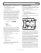
To demonstrate the wide programmable range of the loop filter
bandwidth, consider the following design example. The system
clock frequency (f
S
) is 1 GHz, the input reference frequency (f
R
)
is 19.44 MHz, the DDS output frequency (f
DDS
) is 155.52 MHz,
and the required phase margin (Φ) is 45°. f
R
is within the nominal
bandwidth of the phase detector (25 MHz), and f
DDS
/f
R
is an integer
(8), so the prescaler is not required. Therefore, R = 1 and S = 8 can
be used for the feedforward and feedback dividers, respectively.
Note that if f
DDS
/f
R
is a noninteger, then R and S must be chosen
such that S/R = f
DDS
/f
R
with S and R both constrained to integer
values. For example, if f
R
= 10 MHz and f
DDS
= 155.52 MHz,
then the optimal choice for S and R is 1944 and 125, respectively.
The open-loop bandwidth range under the defined conditions
spans 9.5 Hz to 257.5 kHz. The wide dynamic range of the loop
filter coefficients allows for programming of any open-loop
bandwidth within this range under these conditions. The
resulting closed-loop bandwidth range under the same
conditions is approximately 12 Hz to 359 kHz.
The resulting loop filter coefficients for the upper loop bandwidth,
along with the necessary programming values, are shown as
follows:
α = 4322509.4784981
α
0
= 2111 (0x83F)
α
1
= 22 (0x16)
α
2
= 0 (0x00)
β = −0.10354689386232
β
0
= 3393 (0xD41)
β
1
= 0 (0x00)
γ
0
= 4095 (0xFFF)
γ = −0.12499215775201
γ
1
= 0 (0x00)