
Datasheet


AD9549
Rev. D | Page 22 of 76
Phase Detector Gain Matching
Although the fine and coarse phase detectors use different means
to make a timing measurement, it is essential that both have
equivalent phase gain. Without proper gain matching, the
closed-loop dynamics of the system cannot be properly
controlled. Hence, the goal is to make PhaseGain
CPD
=
PhaseGain
FPD
.
This leads to
GainFPFDPDGf
PDS
S
_)102()2(
7106
×=
+
which simplifies to
S
PDS
f
GainFPFD
PDG
_)1016(
2
7
×
=
Typically, FPFD_Gain is established first, and then PDG and
PDS are calculated. The proper choice for PDS is given by
×
=
S
f
GainFPFD
PDS
2
_10
loground
7
2
The final value of PDS must satisfy 0 ≤ PDS ≤ 7. The proper
choice for PDG is calculated using the following equation:
=
−
S
PDS
f
GainFPFD
PDG
4
7
2
_10
round
The final value of PDG must satisfy 0 ≤ PDG ≤ 63. For example,
let f
S
= 700 MHz and FPFD_Gain = 200; then PDS = 1 and
PDG = 23.
Note that the AD9549 evaluation software calculates register
values that have the phase detector gains already matched.
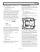
Phase Detector Pin Connections
There are three pins associated with the phase detector that
must be connected to external components. Figure 27 shows the
recommended component values and their connections.
06744-027
10µF
0.1µF
PFD_VRT PFD_RSETPFD_VRB
AD9549
0.1µF
0.1µF
4.99kΩ
20 21 22
Figure 27. Phase Detector Pin Connections
DIGITAL LOOP FILTER COEFFICIENTS
To provide the desired flexibility, the loop filter has been
designed with three programmable coefficients (α, β, and γ).
The coefficients, along with P (where P = 2
PIO
), completely
define the response of the filter, which is given by
++−−+
−−+
=
)1()2(
)1(
)(
2
γeγe
γβe
αωH
jωωj
jω
LoopFilter
To evaluate the response in terms of absolute frequency, substitute
S
f
Pf
ω
π
=
2
where P is the divide ratio of the P-divider, f
S
is the DAC sample
rate, and f is the frequency at which the function is to be evaluated.
The loop filter coefficients are determined by the AD9549
evaluation software according to three parameters:
• Φ is the desired closed-loop phase margin (0 < Φ < π/2 rad).
• f
LOOP
is the desired open-loop bandwidth (Hz).
• f
DDS
is the desired output frequency of the DDS (Hz).
Note that f
DDS
can also be expressed as f
DDS
= f
R
(S/R).
The three coefficients are calculated according to parameters
via the following equations:
)tan(4 ΦPfβ
C
π−=
βΦFγ )(
2
1
=
βΦFff
GainFPFD
α
CDDS
)(
_10
2
7
38
π
−=
where:
)sin(
1
1)(
Φ
ΦF +=
S
LOOP
C
f
f
f =
FPFD_Gain is the value of the gain scale factor for the fine
phase detector as programmed into the I/O register map.
Note that the range of loop filter coefficients is limited as follows:
0 < α < 2
23
(~8.39 × 10
6
)
−0.125 < β < 0
−0.125 < γ < 0
The preceding constraints on β and γ constrain the closed-loop
phase margin such that both β and γ assume negative values.
Even though β and γ are limited to negative quantities, the values as
programmed are positive. The negative sign is assumed internally.
Note that the closed-loop phase margin is limited to the range
of 0° < Φ < 90° because β and γ are negative.