
Datasheet


AD9246
Rev. A | Page 30 of 44
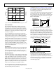
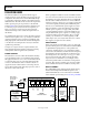
1. Remove C1 and C2 in the default analog input path.
2. Populate R3 and R4 with 200 Ω resistors in the analog
input path.
3. Populate the optional amplifier input path with all
components except R594, R595, and C502. Note that
to terminate the input path, only one of the following
components should be populated: R9, R592, or the
combination of R590 and R591.
4. Populate C529 with a 5 pF capacitor in the analog input path.
Currently, R561 and R562 are populated with 0 Ω resistors to
allow signal connection. This area allows the user to design a
filter, if additional requirements are necessary.