
Datasheet


AD8479 Data Sheet
Rev. 0 | Page 14 of 16
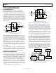
OUTPUT FILTERING
To limit noise at the output, a simple two-pole, low-pass Butter-
worth filter can be implemented using the ADA4077-2 after the
AD8479, as shown in Figure 39.
REF(–)
REF(+)
–V
S
–V
S
+V
S
+V
S
+V
S
V
OUT
NC
–IN
+IN
0.1µF
0.1µF
0.1µF
0.1µF
NC = NO CONNECT
AD8479
1
2
3
4
8
7
6
5
R1
R2
C2
ADA4077-2
C1
11118-039
Figure 39. Filtering Output Noise Using a Two-Pole Butterworth Filter
Table 5 provides recommended component values for various
corner frequencies, along with the peak-to-peak output noise
for each case.
GAIN OF 60 DIFFERENTIAL AMPLIFIER
Low level signals can be connected directly to the −IN and +IN
inputs of the AD8479. Differential input signals can also be con-
nected to give a precise gain of 60 (see Figure 40); however, large
common-mode voltages are no longer permissible. Cold junction
compensation can be implemented using a temperature sensor,
such as the AD590.
REF(–)
REF(+)
+V
S
+V
S
NC
–IN
+IN
0.1µF
NC = NO CONNECT
AD8479
1
2
3
4
8
7
6
5
V
OUT
V
REF
THERMOCOUPLE
11118-041
Figure 40. Gain of 60 Thermocouple Amplifier
Table 5. Recommended Values for Two-Pole Butterworth Filter
Corner Frequency R1 R2 C1 C2 Output Noise (p-p)
50 kHz
2.94 kΩ ± 1%
1.58 kΩ ± 1%
2.2 nF ± 10%
1 nF ± 10%
2.9 mV
5 kHz 2.94 kΩ ± 1% 1.58 kΩ ± 1% 22 nF ± 10% 10 nF ± 10% 0.9 mV
500 Hz 2.94 kΩ ± 1% 1.58 kΩ ± 1% 220 nF ± 10% 0.1 µF ± 10% 0.296 mV
50 Hz 2.7 kΩ ± 10% 1.58 kΩ ± 10% 2.2 µF ± 20% 0.1 µF ± 20% 0.095 mV
No Filter 4.7 mV