
Datasheet

AD8122 Data Sheet
Rev. 0 | Page 16 of 20
When using a single 5 V supply on the driver side, the common-
mode voltage at the driver output is typically 2.5 V (in the case
of the AD8142 driver, the common-mode voltage at the output
is fixed at 1.5 V). The largest received differential video signal is
approximately 700 mV p-p, which adds 175 mV
PEAK
to each single-
ended side of the differential signal and results in a worst-case
peak voltage of 2.675 V or 1.675 V on an AD8122 single-ended
input (assuming that there is no ground shift between the driver
and receiver). Because these levels are within the AD8122 input
voltage swing limits, such a system works well as long as the
difference in ground potential between the driver and receiver
does not cause the input voltage swing to exceed these limits.
When used, common-mode sync signals are generally applied
with a peak deviation of 500 mV during the blanking intervals
(video signal = 0 V), increasing the common-mode level from
2.5 V to 3.0 V (1.5 V to 2.0 V in the case of the AD8142 driver).
These common-mode levels are below the upper input voltage
swing limit of 4 V and, therefore, leave a margin of 1 V or 2 V
for ground shifts between the driver and receiver. To increase
the common-mode range of the overall system, use one or both
of these techniques:
• Power the driver from dual supplies (output common-mode
voltage = 0 V).
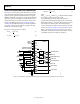
• Place an AD8143 in front of the AD8122, as shown in
Figure 31.
These techniques can be combined or applied separately.
POWER-DOWN
The power-down feature can be used to reduce power consump-
tion when a particular device is not in use. When asserted, the
PD
pin does not place the output in a high-Z state. The input
logic levels and supply current in power-down mode are listed
in Table 1.