
Datasheet


Data Sheet AD8122
Rev. 0 | Page 13 of 20
APPLICATIONS INFORMATION
BASIC OPERATION
The AD8122 is easy to apply because it contains on chip all
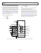
components needed for cable loss compensation. Figure 30
shows a basic application circuit for common-mode sync pulse
extraction that is compatible with the common-mode sync pulse
encoding technique used in the AD8134, AD8142, AD8147,
and AD8148 triple differential drivers. If sync pulse extraction
is not required, the terminations can be single 100 Ω resistors,
and the comparator inputs can be left floating.
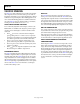
INPUT OVERDRIVE RECOVERY AND PROTECTION
Occasional large differential transients can occur on the cable
due to a number of causes, such as ESD and switching. When
operating the AD8122 at G = 1, a differential input that exceeds
+3.4 V or −3.4 V causes the output to “stick” at the associated
power supply rail (positive rail for positive overdrive, negative
rail for negative overdrive). The overdrive condition does not
occur in applications with G = 2.
The AD8122 recovers from the overdrive condition when the
magnitude of the differential input falls below 200 mV. Most
video signals return to 0 V nominal during the blanking intervals;
therefore, recovery from the overdrive condition in systems that
use these signals occurs during the first blanking interval after
the overdrive event has ended.
In systems with G = 1 and video signals that do not return to
0 V—for example, systems that include dc offsets—it is necessary
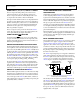
to prevent the overdrive condition from occurring. Figure 28 shows
a protection circuit that limits the differential input voltage to a
little over ±2 V. This circuit should be placed between the termina-
tion resistors and each AD8122 differential input.
49.9Ω
1
6
2
5
3
4
HN2D02FUTW1T1G
1
6
2
5
3
4
HN2D02FUTW1T1G
TERMINATION
RESISTORS
AD8122
INPUT
49.9Ω
10780-022
Figure 28. Required Input Protection for Applications with G = 1
COMPARATOR APPLICATIONS
The two on-chip comparators are most often used to extract
video sync pulses from the received common-mode voltages
(see the Sync Pulse Extraction Using Comparators section).
However, the comparators can also be used to recover sync
pulses in sync-on-color applications, to receive differential
digital information received on other channels such as the
fourth UTP pair, or as general-purpose comparators. Built-in
hysteresis helps to eliminate false triggers from noise.
An ideal source terminated transmission line has a source
resistance that exactly matches the characteristic impedance of
the line and a load impedance that is infinite. When the signal is
launched into the source termination, the initial value of the signal
is one-half the source value because the signal amplitude is divided
by 2 in the voltage divider formed by the source termination and
the transmission line. At the load, the signal experiences 100%
positive reflection due to the infinite load impedance and is
restored to its full value. This technique is commonly used in
PCB layouts that involve high speed digital logic.
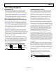
The comparators are designed to drive source terminated
transmission lines and have output resistances of 18 Ω in the
low state and 1 Ω in the high state. Because the output resistances
are different for each state, a compromise must be made in select-
ing the external source termination resistor value to match the
transmission line impedance. The best approximation to a 50 Ω
match that can be achieved in this case is with an external resistor
value of approximately 41.2 Ω, which is available as a standard
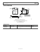
1% value. See Figure 29 for an illustration of the source termina-
tion technique.
Impedance mismatches occur in both the high state and the low
state due to the differences in output resistances, resulting in a
reflection coefficient of approximately +8.4% (21.5 dB return
loss) in the low state, where the total source resistance is 59.2 Ω,
and −8.4% (21.5 dB return loss) in the high state, where the total
source resistance is 42.2 Ω. This source match is acceptable for
digital sync pulses.
Figure 29 shows how to apply source termination to the
comparators when driving a 50 Ω transmission line that is
high impedance at its receive end.
41.2
Ω
HIGH-Z
Z
0
= 50Ω
10780-023
Figure 29. Using a Comparator with Source Termination