
Datasheet


AD8122 Data Sheet
Rev. 0 | Page 12 of 20
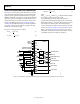
THEORY OF OPERATION
The AD8122 is a triple, wideband, low noise analog line equalizer
that compensates for losses in UTP cables up to 300 meters in
length and coaxial cables up to 200 meters in length. The 3-channel
architecture is targeted at high resolution RGB applications, but
can be used in HD YPbPr applications as well. The transfer func-
tion of the AD8122 can be pin selected for UTP or coaxial cable,
and the gain of each channel can be set to 1 or 2.
ADJUSTABLE CONTROL VOLTAGES
Four continuously adjustable control voltages, common to the
RGB channels, are available to the designer to provide compen-
sation for various cable lengths, as well as for variations in the
cable itself.
• The V
PEAK
pin is used to control the amount of high fre-
quency peaking. The V
PEAK
control is used to compensate
for frequency dependent losses and cable length dependent
losses that are present due to the skin effect of the cable.
• The V
GAIN
pin is used to adjust broadband gain to com-
pensate for low frequency flat losses present in the cable.
• The V
FILTER
pin is used to adjust the cutoff frequency of the
output low-pass filters.
• The V
OFFSET
pin is an output offset adjustment control that
allows the designer to shift the output dc level.
DIFFERENTIAL INPUTS
The AD8122 has high impedance differential inputs that make
termination simple and allow dc-coupled signals to be received
directly from the cable. The AD8122 inputs can also be used in a
single-ended fashion in coaxial cable applications. For differen-
tial systems that require a very wide input common-mode range,
the AD8143 high voltage, triple differential receiver can be placed
in front of the AD8122. For more information, see the Input
Common-Mode Range section.
OUTPUTS
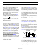
The AD8122 has low impedance outputs that are capable of
driving a 150 Ω load. In systems where the AD8122 must drive
a high impedance capacitive load, it is recommended that a small
series resistor be placed between the output and the load to buffer
the capacitance. The resistor should not be so large as to reduce
the overall bandwidth to an unacceptable level. For more informa-
tion, see the Driving High Impedance Capacitive Loads section.
ON-CHIP COMPARATORS
Two on-chip comparators can be used for sync pulse extraction
in systems that use common-mode sync pulse encoding (see the
Sync Pulse Extraction Using Comparators section).
Each comparator can be used in a source-only cable termination
scheme by placing a resistor in series with the comparator output.
For more information, see the Comparator Applications section.
INPUT SINGLE-ENDED VOLTAGE RANGE
CONSIDERATIONS
When using the AD8122 as a receiver, it is important to ensure
that its single-ended input voltages stay within their specified
ranges. The received single-ended level for each input is calcu-
lated by adding the common-mode level of the driver, the single-
ended peak amplitude of the received signal, the amplitude of
any sync pulses, and other induced common-mode signals, such
as ground shifts between the driver and the
AD8122 and pickup
from external sources, such as power lines and fluorescent lights.
For more information, see the Input Common-Mode Range
section.