
Datasheet


Table Of Contents
AD8027/AD8028
Rev. C | Page 22 of 24
BAND-PASS FILTER
In communication systems, active filters are used extensively in
signal processing. The AD8027/AD8028 are excellent choices
for active filter applications. In realizing this filter, it is impor-
tant that the amplifier have a large signal bandwidth of at least
10× the center frequency, f
O
. Otherwise, a phase shift can occur
in the amplifier, causing instability and oscillations.
In
Figure 62, the AD8027/AD8028 part is configured as a
1 MHz band-pass filter. The target specifications are f
O
= 1 MHz
and a −3 dB pass band of 500 kHz. To start the design, select f
O
,
Q, C1, and R4. Then use the following equations to calculate the
remaining variables:
(MHz)
(MHz)
PassBand
f
Q
O
=
k = 2πf
O
C1
C2 = 0.5C1
R1 = 2/k, R2 = 2/(3k), R3 = 4/k
H = 1/3(6.5 – 1/Q)
R5 = R4/(H – 1)
+5
–5
C3
0.1
μ
F
C4
0.1
μ
F
R4
523
Ω
R5
523
Ω
C2
500pF
C1
1000pF
R3
634
Ω
V
OUT
R1
316
Ω
R2
105
Ω
V
IN
SELECT
AD8027/
AD8028
+
–
03327-A-061
Figure 62. Band-Pass Filter Schematic
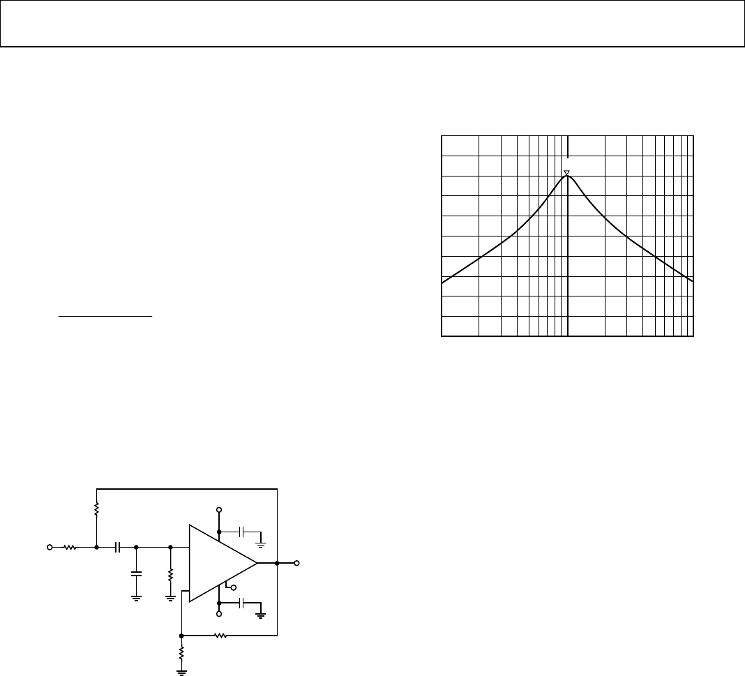
The test data shown in Figure 63 indicates that this design
yields a filter response with a center frequency of f
O
= 1 MHz,
and a bandwidth of 450 kHz.
0.1
CH1 S21 LOG 5dB/REF 6.342dB 1:6.3348dB 1.00 000MHz
1
FREQUENCY – MHz
10
1
03327-A-062
Figure 63. Band-Pass Filter Response
DESIGN TOOLS AND TECHNICAL SUPPORT
Analog Devices, Inc. (ADI) is committed to simplifying the
design process by providing technical support and online
design tools. ADI offers technical support via free evaluation
boards, sample ICs, interactive evaluation tools, data sheets,
spice models, application notes, and phone and email support
available at
www. analog.com.