
Datasheet


AD7877 Data Sheet
Rev. D | Page 42 of 44
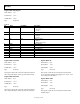
GPIO REGISTERS
GPIO registers are written to using an extended 8-bit address.
The first four bits of the data-word are always 1111b to access
the extended writing map. The next four bits are the register
address. This leaves 8 bits for the GPIO data.
GPIO registers are read like all other registers, by writing a 5-bit
address to Control Register 1, then reading DOUT.
See the GPIO Configuration section for information on
configuring the GPIOs.
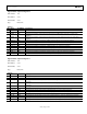
Register Name: GPIO Control Register 1
Write Address: [1111] 0000
Read Address: 11011
Default Value: 0x000
Type: Read/write
Table 22.
Bit Name Read/Write Description
0 GPIO2_ALEN R/W
If this bit is 1, GPIO2 is an interrupt source for the
ALERT output; clearing this bit masks out GPIO2
as an interrupt source for the
ALERT output
1 GPIO2_DIR R/W This bit sets the direction of GPIO2
0 = output
1 = input
2 GPIO2_POL R/W This bit determines if GPIO2 is active high or low
0 = active low
1 = active high
3 GPIO2_EN R/W This bit selects the function of AUX2/GPIO2
0 = AUX2
1 = GPIO2
4 GPIO1_ALEN R/W
If this bit is 1, GPIO1 is an interrupt source for the
ALERT output; clearing this bit masks out GPIO1
as an interrupt source for the ALERT output
5 GPIO1_DIR R/W This bit sets the direction of GPIO1
0 = output
1 = input
6 GPIO1_POL R/W This bit determines if GPIO1 is active high or low
0 = active low
1 = active high
7 GPIO1_EN R/W This bit selects the function of AUX1/GPIO1
0 = AUX1
1 = GPIO1