
Datasheet


Data Sheet AD7877
Rev. D | Page 27 of 44
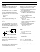
When the DAC output voltage is zero, it sinks the maximum
current through R1. The feedback current and, therefore, V
OUT
are at their maximum. As the DAC output voltage increases, the
sink current and, thus, the feedback current decrease, and V
OUT
falls. If the DAC output exceeds V
REF
, it starts to source current,
and V
OUT
has to further decrease to compensate. When the
DAC output is at full scale, V
OUT
is at its minimum.
Note that the effect of the DAC on V
OUT
is opposite in voltage
mode to that in current mode. In current mode, increasing
DAC code increases the sink current, so V
OUT
increases with
increasing DAC code. In voltage mode, increasing DAC code
increases the DAC output voltage, reducing the sink current.
Calculate the resistor values as follows:
1. Decide on the feedback current as before.
2. Calculate the parallel combination of R1 and R3 when the
DAC output is zero
R
P
= V
REF
/I
FB
3. Calculate R2 as before, but use R
P
and V
OUT(MAX)
R2 = R
P
(V
OUT(MAX)
− V
REF
)/V
REF
4. Calculate the change in feedback current between
minimum and maximum output voltages as before using
∆I = V
R2(MAX)
/R2 − V
R2(MIN)
/R2
This is equal to the change in current through R1 between
zero output and full scale, which is also given by
∆I = current at zero − current at full scale
= V/R1 − (V
REF
− V)/R1
= V/R1
5. R1 = V
FS
/∆.
6. Calculate R3 from R1 and R using
R3 = (R1 × R
P
)/(R1 − R
P
)
Example:
1. V
CC
= 5 V and V
FS
= V
CC
. V
OUT(MIN)
is 20 V and V
OUT(MAX)
is
25 V. V
REF
is 1.25 V. Allow 100 µA around the feedback loop.
2. R
P
= 1.25 V/100 µA = 12.5 kΩ.
3. R2 = 12.5 kΩ × (25 Ω − 1.25 Ω)/1.25 Ω = 237 kΩ.
Use the nearest preferred value of 240 kΩ.
4. ∆I = 25 V/240 kΩ − 20 V/240 kΩ = 21 µA.
5. R1 = 5 V/21 µA = 238 kΩ.
Use the nearest preferred value of 250 kΩ.
6. R3 = (180 kΩ × 12.5 kΩ)/(180 kΩ − 12.5 kΩ) = 13.4 kΩ.
Use nearest preferred value of 13 kΩ.
The actual adjustment range using these values is 21 V to 26 V.