
Datasheet


Data Sheet AD7877
Rev. D | Page 15 of 44
AUX3/GPIO4
BAT1
BAT2
AUX2/GPIO3
AUX1/GPIO2
12-BIT SUCCESSIVE
APPROXIMATION ADC
WITH TRACK-AND-HOLD
9 TO 1
I/P
MUX
TEMPERATURE
SENSOR
Y–
Y+
X–
X+
V
CC
REF–
IN+
REF
INT/EXT
REF+
DUAL 3-1
MUX
X–
Y– GND X+ Y+ V
REF
03796-006
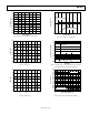
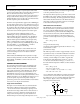
Figure 28. Analog Input Structure
The AD7877 can be set up to automatically convert either
specific input channels or a sequence of channels. The results of
the ADC conversions are stored in the results registers. See the
Serial Interface section for details.
When measuring the ancillary analog inputs (AUX1 to AUX3,
BAT1 and BAT2), the ADC uses the internal reference, or an
external reference applied to the V
REF
pin, and the measurement
is referred to GND.
MEASURING TOUCH SCREEN INPUTS
When measuring the touch screen inputs, it is possible to
measure using the internal (or external) reference, or to use the
touch screen excitation voltage as the reference and perform a
ratiometric, differential measurement. The differential method
is the default and is selected by clearing the SER/
DFR
bit
(Bit 11) in Control Register 1. The single-ended method is
selected by setting this bit.
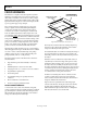
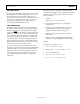
Single-Ended Method
Figure 29 illustrates the single-ended method for the Y position.
For the X position, the excitation voltage is applied to X+ and
X− and the voltage measured at Y+.
03796-007
ADC
REF+
INPUT
(VIA MUX)
X+
REF–
TOUCH
SCREEN
Y+
Y–
GND
V
REF
V
CC
Figure 29. Single-Ended Conversion of Touch Screen Inputs
The voltage seen at the input to the ADC in Figure 29 is
YTOTAL
Y
CC
IN
R
R
VV
−
×=
(1)
The advantage of the single-ended method is that the touch
screen excitation voltage can be switched off once the signal is
acquired. Because a screen can draw over 1 mA, this is a
significant consideration for a battery-powered system.
The disadvantages of the single-ended method are as follows:
• It can be used only if V
CC
is close to V
REF
. If V
CC
is greater
than V
REF
, some positions on the screen are outside the
range of the ADC. If V
CC
is less than V
REF
, the full range of
the ADC is not used.
• The ratio of V
CC
to V
REF
must be known. If V
REF
and/or V
CC
vary relative to one another, this can introduce errors.
• Voltage drops across the switches can introduce errors.
Touch screens can have a total end-to-end resistance
ranging from 200 Ω to 900 Ω. Taking the lowest screen
resistance of 200 Ω and a typical switch resistance of 14 Ω
can reduce the apparent excitation voltage to 200/228 ×
100 = 87% of its actual value. In addition, the voltage drop
across the low-side switch adds to the ADC input voltage.
This introduces an offset into the input voltage, thus, it can
never reach zero.
The single-ended method is adequate for applications that use a
fairly blunt and imprecise instrument for an input device, such
as a finger.
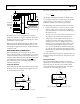
Ratiometric Method
The ratiometric method illustrated in Figure 30 shows the
negative input of the ADC reference tied to Y− and the positive
input connected to Y+. Thus, the screen excitation voltage
provides the reference for the ADC. The input of the ADC is
connected to X+ to determine the Y position.
03796-008
ADC
REF+
INPUT
(VIA MUX)
REF–
V
CC
X+
TOUCH
SCREEN
Y+
Y–
GND
Figure 30. Ratiometric Conversion of Touch Screen Inputs