
User`s guide

August 2012L010185
9
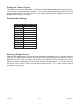
Determine Output Current
The output current used for motor when microstepping is determined differently from that of a
full/half step unipolar driver. In the MBC10SI1, a sine/cosine output function is used in rotating
the motor. The output current for a given motor is determined by the motors current rating and
the wiring confi guration of the motor. There is a current adjustment potentiometer used to set
the output current of the MBC10SI1. This sets the peak output current of the sine/cosine waves.
The specifi ed motor current (which is the unipolar value) is multiplied by a factor of 1.0, 1.4, or
2.0 depending on the motor confi guration (series, half-coil, or parallel).
Step Motor Confi gurations
Step motors can be confi gured as 4, 6, or 8 leads. Each confi guration requires different currents.
Refer to the lead confi gurations and the procedures to determine their output current.
WARNING! Step motors will run hot even when confi gured correctly. Damage may occur to the
motor if a higher than specifi ed current is used. Most specifi ed motor currents are maximum
values. Care should be taken to not exceed these ratings.
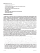
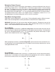
6 Lead Motors
When confi guring a 6 lead motor in a half-coil confi guration (connected from one end of the coil
to the center tap), multiply the specifi ed per phase (or unipolar) current rating by 1.4 to determine
the current setting potentiometer value. This confi guration will provide more torque at higher
speeds when compared to the series confi guration.
When confi guring the motor in a series confi guration (connected from end to end with the cen-
ter tap fl oating) use the specifi ed per phase (or unipolar) current rating to determine the current
setting potentiometer value.
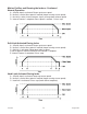
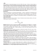
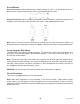
4 Lead Motors
Multiply the specifi ed series motor current by 1.4 to determine the current adjustment potenti-
ometer value. 4 lead motors are usually rated with their appropriate series current, as opposed
to the Phase Current, which is the rating for 6 and 8 lead motors.