
User`s guide

August 2012L010185
4
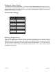
LEDs
When powered and operated properly, the status LED will be green. When a communication or
program syntax error occurs, the LED will change to RED and an error code will be generated in the
error code register. To read and clear the error with the software, click on the “Verify Parameters”
button. To read and clear the error while in “Direct Mode” use the “!” command. Once the error has
been read and cleared, the LED will return to green and the error code register will be cleared. Refer
to the table in the trouble-shooting section for a list of the error codes. When the indexer is running
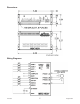
the yellow LED will be on. Refer to the dimension drawing for location of the LEDs. For more detail
on “Direct Mode” Refer to the Direct Talk Mode Section of User’s Guide.
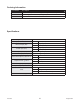
Baud Rates
A term used frequently in serial data communications. A “baud” is defi ned as the reciprocal of the
shortest pulse duration in a data word signal, including start, stop, and parity bits. This is often taken
to mean the same as “bits per second”, a term that expresses only the number of “data” bits per sec-
ond. Very often, the parity bit is included as an information or data bit. The MBC10SI1 only accepts
a baud rate of 38400.
Inputs and Outputs
Inputs: All inputs are pulled up to 5VDC. A logic “0” activates inputs that are pulled up. An uncon-
nected input will always remain inactive.
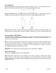
Direction: When this input is not active, the motor will be moving in the clockwise or “+” direction.
When this input is active, the motor will move in the counterclockwise or “-” direction. This input is
not read when a software index command is given. To change direction while using the software,
change the direction option there. When two motors are used, the second motor will move in the
opposite direction by default.
On/Off: When this input is not active, the motor will enabled or energized. When this input is active,
the motor will be disabled or de-energized.
Index 1 and 2: These inputs are used to select on of the two profi les. When one of the profi les is acti-
vated, the unit will change the speeds, acceleration and index number based on the pre-programmed
values for that profi le and begin the index. Activate only one of these two inputs at once.
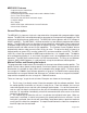
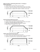
Soft Limits: These two inputs are controlled by the direction of the indexer. When the indexer is
running in the positive direction only soft+ will work. When the indexer is running in the negative
direction then only soft- will work. When pulled low the motor will ramp down to base speed and
continue running until the index is completed or a hard limit is reached.
Hard Limits: These two inputs are controlled by the direction of the indexer. When the indexer is
running in the positive direction only hard+ will work. When the indexer is running in the negative
direction then only hard- will work. When pulled low the indexer will stop all pulses to the motor. To
reverse off of a Hard Limit, change directions, and activate another profi le input again to move in the
opposite direction.
Complete Output: This is an open collector output that is capable of sinking 10mA. It is current
sinking when the indexer completes its motion and is only active for the pre-programmed time.
Busy Output: This is an open collector output that is capable of sinking 10mA. It is current sinking
when the indexer is running and open when the indexer is not running.