
User`s guide

August 2012L010185
10
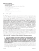
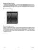
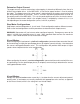
8 Lead Motors
Series Connection: When confi guring the motor windings in series, use the per phase (or uni-
polar) current rating to determine the current setting potentiometer value.
Parallel Connection: When confi guring the motor windings in parallel, multiply the per phase (or
unipolar) current rating by 2.0 to determine the current setting potentiometer value.
Note: After the current has been determined, according to the motor connections above, use
the potentiometer setting table to choose the proper setting for the current setting potentiometer.
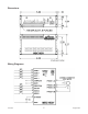
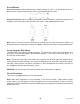
Connecting the Step Motor
The MBC10SI1 is designed to accept one motor. For wiring of the motor refer to the pages con-
taining the connector descriptions and hookups diagrams. The motor is wired into pins 3, 4, 5
and 6 of the terminal block.
Note: The physical direction of the motor with respect to the direction input will depend on the
connection of the motor windings. To reverse the direction of the motor with respect to the direc-
tion input, switch the wires on phase 1 and phase 3. With the operation of 2 motors, they will run
in the opposite direction when wired the same.
WARNING: Do not connect or disconnect motor wires while power is applied!
Circuit Protection
This driver is equipped with over current protection.
Note: When drive experiences a fault condition, it will seize to function. Power down, inspect
wiring, motors, etc. and allow for a 30 second pause to resume functioning. If driver is too hot,
additional ventilation and airfl ow should be added to prevent temperature to exceed recommended
temperature limit.