MBC10SI1 Programmable Simple Indexer/Driver User’s Guide A N A H E I M A U T O M A T I O N 910 East Orangefair Lane, Anaheim, CA 92801 e-mail: info@anaheimautomation.com L010185 1 (714) 992-6990 fax: (714) 992-0471 website: www.anaheimautomation.
MBC10SI1 Features • Output Current of 10.0A Peak • 2000 Steps/Revolution • On-Board Programmable Simple Indexer with 2 Motion Profiles • Pulses From 1Hz to 50kHz • Directional Soft and Hard Limit Switch Inputs • Complete Output • Busy Output • Motor On/Off Input and Automatic Current Reduction • Short Circuit Protection General Description The MBC10SI1 is a low cost single axis step motor driver integrated with a programmable simple indexer.
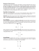
Motion Profiles and Running the Indexer: Continued Normal Operation A. B. C. D. A Profile input is activated; Ramps up to max speed. No limit is active; Max speed is reached (keeps running at max speed). No Limit is active; Internal counter signals to ramp down to base speed. Internal Counter is complete; Base speed is reached. Pulses stop. Soft Limit Activated During Index A. A Profile input is activated; Ramps up to max speed. B. No limit is active; Max speed is reached (keeps running at max speed). C.
LEDs When powered and operated properly, the status LED will be green. When a communication or program syntax error occurs, the LED will change to RED and an error code will be generated in the error code register. To read and clear the error with the software, click on the “Verify Parameters” button. To read and clear the error while in “Direct Mode” use the “!” command. Once the error has been read and cleared, the LED will return to green and the error code register will be cleared.
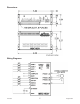
Connector Descriptions Connector P2: Pin # Description L010185 1 Power Supply Ground (0VDC) 2 Power Supply Input (20VDC - 80VDC) 3 Motor Phase 1 (A) 4 Motor Phase 3 (/A) 5 Motor Phase 2 (B) 6 Motor Phase 4 (/B) 7 Index 1 8 Index 2 9 Motor On/Off 10 Direction In 11 Busy Output 12 Complete Output 13 Soft Limit + 14 Soft Limit - 15 Hard Limit + 16 Hard Limit - 5 August 2012
Ordering Information Part Number Description MBC10SI1 10.0A Microstep Driver with Integrated Programmable Simple Indexer PSA80V4A Power Supply for MBC10SI1 (80V @ 4.
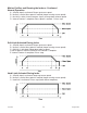
Dimensions Wiring Diagrams L010185 7 August 2012
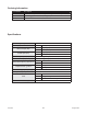
Setting the Output Current The output current on the MBC10SI1 is set by the on-board potentiometer R29 (Refer to Dimensions/Jumper and Potentiometer Locations). This current adjust potentiometer determines the per phase peak output current of the driver. This relationship between the output current and the potentiometer setting is as follows: Potentiometer Settings Peak Current Potentiometer Setting 1.5A 0% 2.4A 10% 3.0A 20% 4.0A 30% 5.2A 40% 6.4A 50% 7.7A 60% 8.7A 70% 9.8A 80% 10.
Determine Output Current The output current used for motor when microstepping is determined differently from that of a full/half step unipolar driver. In the MBC10SI1, a sine/cosine output function is used in rotating the motor. The output current for a given motor is determined by the motors current rating and the wiring configuration of the motor. There is a current adjustment potentiometer used to set the output current of the MBC10SI1. This sets the peak output current of the sine/cosine waves.
8 Lead Motors Series Connection: When configuring the motor windings in series, use the per phase (or unipolar) current rating to determine the current setting potentiometer value. Parallel Connection: When configuring the motor windings in parallel, multiply the per phase (or unipolar) current rating by 2.0 to determine the current setting potentiometer value.
Functions Hard Limit Switches: When a hard limit switch is encountered, the pulses will stop. Hard limits are intended as an emergency stop for your system. Soft Limit Switches: These switches cause the indexer to ramp down to the base speed and finish the index, unless encountering a hard limit switch. Profile Inputs: These inputs are used to select and begin the specified motion profile. Only 1 input should be activated at a time.
SMPG-SMSI Software The SMPG-SMSI software is a handy utility that supports Anaheim Automation’s programmable pulse generators and simple indexers. Connecting your PC to the MBC10SI1, via a serial cable, the software can easily perform the following tasks: • Exercise and monitor the MBC10SI1 • Directly communicate with the MBC10SI1 Installation Software • The SMPG-SMSI software is supplied on a CD, containing the setup program and the software.
“The Unit is Connected” / “The Unit is Not Connected” On the right of the Toolbar, the user will find the communication status of the indexer. If communications is not established, please refer to the troubleshooting section. File Menu Setup Menu Exit Connect Disconnect Exit the SMPG10WIN Software Establish communications with the controller. Discontinue communications and release the comport for use by other devices. Communication Settings...
Program Window Motion Profile Select motion profiles 1, or 2. Send Accel/Decel Send the acceleration & deceleration parameter to the indexer. (steps/sec2) Send Base Spend Send the base speed parameter to the indexer. (steps/sec) Send Max Speed Send Index Number Begin Motion Send the maximum speed parameter to the indexer. (steps/sec) Send the index number parameter to the indexer. (steps) Motor will ramp up to maximum speed and keep moving until a limit switch is triggered or the index is complete.
Direct Talk Mode Direct mode is used to directly control the motion for real time movements through serial communication. The indexer has 14 commands which are easy to remember for direct movement of a step motor. COM Port Settings Baud Rate: 115200 Parity: None Data Bits: 8 Stop Bits: 1 Flow Control: Xon/Xoff Unit Selection In order to select a unit the @ command followed by 0 (address of the unit) must be sent. NOTE: There should be no spaces between the @ and the 0.
$ - Version Number Register Format: $ Description: This command request the pulse generator to return the version number. ! - Error Codes Register Format: ! Description: This command requests the pulse generator to get the current error code and print it to screen. +/- - Direction Format: + or - Description: This command sets the direction output. A “+” sets the output to clockwise, and a “-” set the output to counterclockwise. This must be done when the indexer is not busy.
C - Current Reduce Option Format: C# - where # is 0 or 1 Description: This command enables the driver to reduce current after pulses are done being sent. A 1 will enable current reduction, and a 0 will disable current reduction. This value is saved in the EEProm for standalone use. G - Go Slew (Run) Format: G# - where # is the speed profile number 1 or 2 Description: This command will send clocks out to the indexer. The only command that can stop the clocks is H (stop motion).
S - Stop Soft Format: S Description: This command will cause the indexer to ramp down to base speed and run until the index is complete or a hard limit is activated. It can only be used when pulses are running. T - Complete Time Format: T#_[value] - where # is the motion profile number 1 or 2 Sample: T1_100 Complete Time of profile 1 equals 100 Description: This command sets the time for an active complete signal after the unit has finished indexing for the motion profile.
Visual Basic Direct Mode Programming Examples Example 1: This Example is for Axis=0, and Profile=1 DimConst DefaultTimeout As Single = 0.5 frmMain.MSComm1.Output = “@0A1_100000” & Chr$(13) Pause DefaultTimeout frmMain.MSComm1.Output = “@0B1_1000” & Chr$(13) Pause DefaultTimeout frmMain.MSComm1.Output = “@0M1_4000” & Chr$(13) Pause DefaultTimeout frmMain.MSComm1.Output = “@0N1_500” & Chr$(13) Pause DefaultTimeout frmMain.MSComm1.Output = “@0T1_100” & Chr$(13) Pause DefaultTimeout frmMain.MSComm1.
Troubleshooting Problem: Can not establish communications with the unit. Possible Solutions: 1. Make sure the indexer has power. Is the Green LED on. 2. Check USB connections. 3. Check for loose cable connection either on the pulse generator or COM Port. 4. Was the software installed successfully? 5. Go to Setup│ Communication Settings and verify COM Port settings. 6. Click on Connect icon to communicate with the unit. 7. If problems still exist, contact Anaheim Automation Tech Support.
Error Codes Error Code Type Description Receive Overflow The serial communications had a receiving error. This is an Error internal error caused by the computer. 1 2 Range Error 4 Command Error 8 Transmit Error 16 Motor Error There was an invalid number of characters sent to the pulse generator. Check to see if the parameters are invalid for the command that was sent. A bad command was sent to the pulse generator.
COPYRIGHT Copyright 2012 by Anaheim Automation. All rights reserved. No part of this publication may be reproduced, transmitted, transcribed, stored in a retrieval system, or translated into any language, in any form or by any means, electronic, mechanical, magnetic, optical, chemical, manual, or otherwise, without the prior written permission of Anaheim Automation, 910 E. Orangefair Lane, Anaheim, CA 92801.