
Specifications


SECTION 2 QUICK START
9
STEP 6a - Set up the Communication Slide Switch to RS232
Refer to Figure 2 (silkscreen) on the side of the Driver Pack for the slide switch placement
STEP 6b - Set up Unit Number
STEP 6c - Set up the Baud Rate
To locate the Baud Rate Switch (SW4) refer to Figure 2. It is the silkscreened table on the Driver Pack.
Note: the default is 9600 ( position 5) on the Baud Rate Switch (SW4). Refer to Section 5, page 23 for
further assistance when selecting the Baud Rate.
STEP 6d - Power-up the Driver Pack
Plug in the Driver Pack. Standard models DPD/DPF7240_ Series, DPFEN403, DPF11401 and DPD60401
are supplied with a detachable linecord which is plugged into a standard wall socket (115VAC, 60 Hz).
The above models are available with a X250 suffix. These units are configured to accept a wide variety of
voltages. You must configure the terminal block to handle the desired voltage level. (Refer to Section 4,
page 26 for X250 Version).
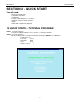
STEP 6e - Press the Connect Icon Button
If everything is connected properly, a green “Connected” indicator will be displayed on the top right hand of
the screen.
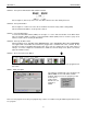
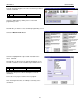
STEP 7 - Write a Program
The Software automatically comes up with the file
SMC40.MDB selected. This will be a blank
program. When you save the program you will
need to give it
another name.
We will save our
program as
TEST1.
There are four program areas that your program may reside in. You will be using the Main Program Area for this
test program.
Refer to Figure 2 or silkscreen on the side of the Driver Pack for the rotary switch setting (SW3).
Note the Default Unit Address 0 corresponds to Axis X.
êê