
Specifications


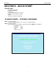


SECTION 2 QUICK START
8
STEP3 - Connect a Motor
Connect the step motor. Use Section 3, Motor Hook Up to assist. Set the Kick Current to match the
motors rated phase current. The kick current potentiometer is located on the driver side labeled Kick
Current Adjust. Whenever you are connecting wires to the Driver Pack, be certain that the power is
off or significant damage can occur.
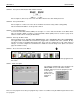
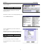
STEP 4 - Connect the Switch and (Optional) LED
This switch is used as a “start switch” to cause the Driver Pack to begin sequencing through the program.
Connect one side of the switch to Pin #1 (Input #1) and the other side of the switch to Pin #5 (0 VDC).
The LED is optional. The LED demonstrates how an Output can be turned on and off. Connect the
Anode side of the LED to Pin # 11 (+5 VDC) and the Cathode side of the LED to Pin #13. Note: A
resistor must be placed in series with the LED to limit the current. A +5V LED has the series resistor
internally connected.
Pin # Description Pin # Description
1 Input #1 10 0 VDC
2 Input #2 11 +5 VDC
3 Input #3 12 Clamp
4 Input #4 13 Output #1
5 0 VDC 14 Output #2
6 Input #5 15 Output #3
7 Input #6 16 Output #4
8 Input #7 17 0 VDC
9 Input #8
Table 3: Connector TB3 Pinout
Figure 1: Connect the Switch and LED
STEP 5 - Connect the Serial Cable to the Driver Pack
To connect your computer to the Driver Pack you need to connect the serial ports (usually COM1 or
COM2) to the units lower DB9 connector. This connector is labeled RS232/RS422 IN (P1). It is helpful
to know which communications port (Com Port) is in use when we setup the software. In most
computers, a 9 pin Male to Female cable will work.
Figure 2: SMC40 Indexer