
Specifications


SECTION 6 COMMUNICATIONS
34
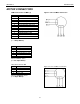
RS422
9 Pin Connector
FUNCTION DESCRIPTION
1 SG signal ground
2 CTS+ clear to send
3 CTS- clear to send-
4 TD+ transmit data+
5 TD- transmit data-
6 RTS+ request to send+
7 RTS- request to send-
8 RD+ receive data+
9 RD- receive data-
TABLE 13: RS422 Connector Pinout
HANDSHAKING SIGNALS
There are two "handshaking" signals: RTS (Request to Send) and CTS (Clear to Send). Some devices
use these handshaking signals and others do not. It is important to know if your device supports certain
handshake signals. Anaheim Automation Indexers support both of these signals.
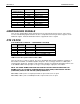
DTE VS DCE
(THE COMPUTER IS THE DTE......THE INDEXER IS THE DCE)
Signal 9 PIN
Connector
DIRECTION FUNCTION
SG 5 0 VDC Signal Ground
TD 3 DTE to DCE transmitted data
RD 2 DCE to DTE received data
RTS 7 DTE to DCE request to send (DTE ready)
CTS 8 DCE to DTE clear to send (DCE ready)
TABLE 14: Pin Description for RS232 with a DB9
There are two types of devices defined. The first is called DTE (data terminal equipment). Examples of
this would be a terminal, or an IBM Compatible Computer. The second type of device is a DCE (data
communication equipment). Examples of this would be a modem or an Anaheim Automation Indexer such
as the SMC40. DTE's have input pins of one type corresponding to output pins on the DCE's.
NOTE: THE SIGNAL NAMES ARE FROM THE POINT OF VIEW OF THE DTE COMPUTER. FOR
EXAMPLE, PIN 3 IS CALLED TD (TRANSMIT DATA) BY BOTH SIDES, EVEN THOUGH THE DTE
(COMPUTER) SENDS IT AND THE DCE (SMC40) RECEIVES IT.
With a DB9, a DTE (such as a computer) transmits on pin 3 and receives on pin 2.
With a DB9, a DCE (such as a SMC40) transmits on pin 2 and receives on pin 3.