
Specifications
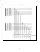


SECTION 5 INSTALLATION
28
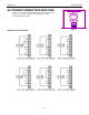
Pin # Description Pin # Description
1 Input #1 10 0 VDC
2 Input #2 11 +5 VDC
3 Input #3 12 Clamp
4 Input #4 13 Output #2
5 0 VDC 14 Output #3
6 Input #5 15 Output #4
7 Input #6 16 Output #5
8 Input #7 17 0 VDC
9 Input #8
Table 7: Connector TB3 Pinout
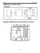
SINGLE AXIS INDEXER CONNECTIONS
Pin # Description
1 +5 VDC
2 Encoder X: Channel A
3 Encoder X: Channel B
4 Encoder X: Channel Z/Marker/Index
5 0 VDC
6 X: Hard-
7 X: Soft
8 X: Home
9 X: Hard+
10 0 VDC
11 X: CLK (Available on PCL401 ONLY)
12 X: DIR (Available on PCL401 ONLY)
13 X: PWR (Available on PCL401 ONLY)
14 0 VDC (Available on PCL401 ONLY)
Table 6: Connector TB2 Pinout
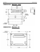
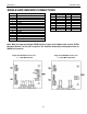
Note: Both the Input and Output 50PIN Headers require a flat ribbon cable and the 50PIN
Breakout Boards if all the I/O is required. The Anaheim Automation Catalog describes all
SMC40 Accessories.
Single Axis DPD72401 Connectors Single Axis DPD60401 Connectors
1 - 7 Amp Bilevel Driver 1 - 6 Amp Microstep Driver