
User`s guide
January 2013L010149
Specifi cations
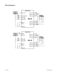
Control Inputs:
TTL-CMOS Compatible
Logic “0” = 0 to 0.8 VDC
Logic “1” = 3.5 to 5.0 VDC
Clock Inputs: (Terminals 5 & 6)
Pulse required; 15 microseconds minimum. The clock input is pulled up internally to +5VDC through a
10K Ú resistor for negative going clock input, or pulled down to 0VDC through a 10K Ú resistor for posi-
tive going clock input.
Direction Control: (Terminal 5)
Logic “1” (open) - Clockwise
Logic “0” - Counterclockwise
Excitation Mode Select: (Terminal 8)
Logic “1” - Half-Step
Logic “0” - 2 ö Full-Step
Power ON/OFF: (Terminal 9)
Logic “1” (open) - Motor current on
Logic “0” - Motor current off
Output Current Rating: (Terminals 1, 2, 3, 11, 12 & 13)
6.5Amps per phase, maximum, over the operating voltage and temperature range. Motor phase ratings
of 1.0Amp minimum are required to meet the minimum kick level.
Power Requirements:
Low-Voltage supply (Vlv) typically ranges between 3.5 and 6.5 VDC. The maximum allowable low-voltage
is 10VDC. (See para DETERMINING LOW-VOLTAGE SUPPLY LEVEL).
High-Voltage supply (Vlv) is 55VDC nominal, 10VDC minimum and, 70VDC maximum. (See paragraph
DETERMINING HIGH-VOLTAGE SUPPLY LEVEL).
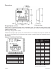
Operating Temperature: (0 to 60°C
It is recommend that the unit be mounted on a larger aluminum plate, or similar heat-conducting structure,
whenever possible. This will prevent the driver from overheating and degrading driver reliability. Fan
cooling is also recommend whenever possible.
The MBL536 requires a power supply kit. Consult the factory for the best driver, power supply and motor
application.
Anaheim Automation offers a color-coded cable for easy step motor hookup.. This 16 gauge, 6
conductor cable is PVC insulated, with color-coded conductors; the same color as the leads on
Anaheim Automation step motors (red, red/white, green, green/white, black and white). The cable
is shield, and available in feet increments, Part Number AA129011-S