
User`s guide

January 2013L010149
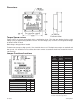
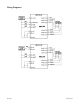
Jumper Functions/Locations
Function JP1 JP2
Terminal 5 = Direction 2 - 3 X
Terminal 5 = CCW 1 - 2 X
Positive Going Clocks X 2 - 3
Negative Going Clocks X 1 - 2
Standard Product 2 - 3 2 - 3
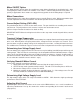
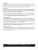
Torque Speed Curves
Torque curves are shown on the back of this specifi cation sheet. This data was obtained using a high
voltage (Vhv) of approximately 60VDC no load. The low voltage (Vlv) used was an unregulated voltage
of about 5.5VDC no load.
Both voltages dropped when loaded.
To obtain more torque at high speeds, Vhv should be increased. To obtain more torque at standstill and
low speeds, Vlv should be increased but the motor current at standstill should not exceed the motor’s
rated current.
Table 1: Jumpers Settings X=Don’t Care
Motor
Part
Number
Current
Rating
(Amps)
VLV Range
23D102 1.0 4.5V - 7.0V
23D104 2.0 3.5V - 5.2V
23D108 3.9 2.5V - 3.3V
23D204 1.8 4.1V - 6.2V
23D209 4.7 2.7V - 3.7V
23D306 2.9 4.0V - 5.9V
23D309 4.6 3.2V - 4.5V
34D106 3.0 3.3V - 4.8V
34D109 4.8 2.7V - 3.8V
34D207 3.5 4.0V - 6.2V
34D209 4.6 3.3V - 4.7V
34D307 3.5 4.0V - 6.0V
34D311 5.5 3.6V - 5.3V
34D314 7.0 3.4V - 4.9V
42D112 6.1 2.9V - 4.0V
42D212 6.1 4.1V - 6.1V
Table 2: Low Voltage Values for
Anaheim Automation Step Motors.
Dimensions