
User`s guide
January 2013L010149
Motor ON/OFF Option
The Motor ON/OFF option allows de-energizing a motor without disturbing the positioning logic. After
reenergizing the motor, a routine can continue. This reduces motor heating and conserves power, es-
pecially in applications where motors are stopped for long periods and no holding torque is required.
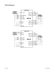
Motor Connections
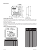
Hookup diagrams for a motor driver application are presented in Figure 3 and 4. Wiring connected to input
must be separated from motor connections and all other possible sources of interference.
Current Adjust Setting (CUR. ADJ.)
The potentiometer R16 is used to set the motor current. The pot should be set according to the motor’s
rated current. This will produce a kick current of 1.4 times the rated motor current.
(Refer to Jumper Functions/Locations for details on R16)
IMPORTANT NOTE: When the wiring from the driver to the step motor extends beyond 25feet, consult
the factory.
Transient Voltage Suppression
Transient Voltage Suppression (TVS) Diodes on the motor phase outputs allow for much longer motor cables
to be used. Normally when using long motor cables, voltage transients and spikes are created. These
transient often exceed the voltage ratings of the output phase transistors, resulting in blown transistors.
The addition of the TVS Diodes suppresses these transients and protect the transistors against damage.
Determining Low-Voltage Supply Level
The Low Voltage (Vlv) supply furnishes the current necessary for holding (standstill) torque and low-speed
running torque. Table 2 shows the current ranges for all compatible Anaheim Automation motors. Higher
values for the Low Voltage will produce more holding and low-speed torque. A proper Vlv will produce a
standstill current that is 65 to 100% of the rated motor current (i.e. for a motor rated at 1 amp, Vlv should
be set so that the standstill current is 0.65 to 1 amps).
Verifying Standstill Motor Current
To check the standstill current do the following:
1. Apply power to the driver with motor connected, but do not apply clock pulses.
2. Select Full-Step mode (ground terminal 8 to 0V). This will assure that two phases will be on.
3. Measure the voltage across resistors R1 and R2.
4. Multiply the readings by 20 to calculate the standstill current. (i.e. if the voltage across R1 and
R2 reads 0.250V, the standstill current is 0.250x20=5.00Amps)
Determining High-Voltage Supply Level
The high-voltage supply (Vhv) can range from 24VDC to 70VDC. VHV determines high-speed torque
performance and acceleration.
Adjusting Kick Current
By following the silkscreen instructions on the cover of the MBL536 driver, use a small screwdriver to
adjust the potentiometer. Line up the arrow to the number corresponding to the motor’s rated current
(amps/phase).