
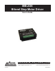
User`s guide
January 2013L010149
General Description
The Anaheim Automation MBL536 is an improved version of the MBL500 series step motor drivers. The
MBL536 with its compactness and attractive rugged packaged style employs bilevel (or dual voltage)
drive technique for high performance operation of step motor providing signifi cantly improved motor speed
torque output. New features include selectable “+” or “-” going clock inputs, transient voltage protection,
and improved Full-step operation.
Bilevel Drive
The basic function of a step motor driver is to control the motor winding currents. Motor performance is
determined by how fast the driver can increase and decrease the winding currents. A rapid rise in winding
current is achieved by applying a high voltage directly to a motor. This rapid rise of current is also referred
to as the “kick” or operating current. When a desired current level is reached, a low voltage is applied to
maintain a suitable holding current level. When a motor winding is turned off, a rapid decrease in winding
current is achieved by routing the energy in the collapsing fi eld back to the power supply through a high
voltage path. The high voltage supply furnishes the energy necessary to maintain motor output torque at
high mechanical power output. The low voltage supply provides much of the current needed at low step
rates and all of the holding current.
Excitation Mode Option
Users have a choice of dual-phase, full-step operation or half-step operation. Dual-phase, full-step opera-
tion occurs by energizing two phases at a time, rotating a typical motor 1.8° per step. Half-step operation
occurs by alternately energizing one, and then two, phases at a time, rotating the motor 0.9° per step.
Half-step is the recommended mode of operation. Full-Step Operation is only suggested for applications
that specifi cally require that mode, such as when retrofi tting existing full-step systems.
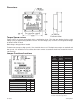
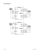
Step and Direction Control
The MBL536 has two clock options: Clock and Direction or Dual Clock operation. Terminal 5 can be
confi gured as the Direction Input or CCW Clock Input by placing jumper JP1 in the appropriate position
(see Table 1 and Figure 2). Pulses applied to the Clock Input cause the motor to step in the clockwise
direction if the Direction Input is a logic “1” or the counterclockwise direction if the Direction Input is a logic
“0”.v Pulses applied to the CCW Input cause the motor to step in the counterclockwise direction. Either
positive or negative going pulses may be used by setting JP2 to the appropriate position (See Table 1
and Figure 2).
MBL536 Features
• 10 Amperes/Phase Maximum Operating Current
• 7 Amperes/Phase Standstill Motor Current
• Half-Step and Full-Step Operation
• Bilevel Drive Operation
• No RFI or EMI Problems
• TTL/CMOS Compatible Inputs
• Clock and Direction or Dual Clock Operation
• Motor Turn-Off Input
• Compact and Rugged