Product Data Sheet October 2014 00813-0100-4530, Rev FA Rosemount 5300 Series Superior Performance Guided Wave Radar Level and Interface Transmitter Industry leading measurement capability and reliability provided by direct switch technology Reduced instrument count and process penetrations with a MultiVariable™ transmitter Increased plant availability with advanced diagnostics and PlantWeb™ functionality Improved EMC performance and higher safety with smart galvanic interface Ideal for
October 2014 Rosemount 5300 Series Taking guided wave radar benefits to the next level Measurement principle Reference pulse Level Low power, nano-second microwave pulses are guided down a probe submerged in the process media. When a microwave pulse reaches a media with a different dielectric constant, part of the energy is reflected back to the transmitter. Interface level The transmitter uses the residual wave of the first reflection for measuring the interface level.
October 2014 Rosemount 5300 Series Special 5300 features Displacer Guided Wave Radar Optimized to suit more applications Suitable for most liquid and solids level applications and liquid interface applications Innovations to handle even the most challenging applications reliably, including process vessels, control, and safety A wide selection of materials, process connections, probe styles, and accessories A wide range of options to find the best fit in existing chambers, or a complete a
October 2014 Rosemount 5300 Series Easy installation and plant integration Secondary gas tight seal decoupled from the process Flexible probe load and locking system Dual ceramic temperature and pressure seal Easy upgrade by matching existing tank connections and cut-to-fit probes Long lengths of rigid probes for robust measurements becomes cost-effective and practical to ship, store and install with the segmented probe option (code 4S) MultiVariable device reduces the number of process penetr
October 2014 Rosemount 5300 Series Rosemount 5301 and 5302 Level and/or Interface in Liquids Ordering Information Rosemount 5301 and 5302 Guided Wave Radar Level transmitters provide industry leading measurement capabilities and reliability in liquids.
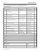
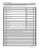
October 2014 Rosemount 5300 Series Table 1. 5301 and 5302 Level and/or Interface in Liquids Ordering Information The starred options (★) represent the most common options and should be selected for best delivery. The non-starred offerings are subject to additional delivery lead time.
October 2014 Rosemount 5300 Series Table 1. 5301 and 5302 Level and/or Interface in Liquids Ordering Information The starred options (★) represent the most common options and should be selected for best delivery. The non-starred offerings are subject to additional delivery lead time. Probe type 3B Coaxial, perforated. For level and interface measurement. Process connection (8) Flange / 1-in. , 1½-in., 2- in.(8) Thread Min: 1 ft 4 in. (0.4 m) Max: 19 ft 8 in. (6 m) ★ Flange Min: 2 ft 11 in. (0.
October 2014 Rosemount 5300 Series Table 1. 5301 and 5302 Level and/or Interface in Liquids Ordering Information The starred options (★) represent the most common options and should be selected for best delivery. The non-starred offerings are subject to additional delivery lead time. AC 2 in., 600 lb H, P, C ★ AD 2 in., 900 lb H, P, C ★ BA 3 in., 150 lb S, H, P, C ★ BB 3 in., 300 lb S, H, P, C ★ BC 3 in., 600 lb H, P, C ★ BD 3 in., 900 lb H, P, C ★ CA 4 in.
October 2014 Rosemount 5300 Series Table 1. 5301 and 5302 Level and/or Interface in Liquids Ordering Information The starred options (★) represent the most common options and should be selected for best delivery. The non-starred offerings are subject to additional delivery lead time.
October 2014 Rosemount 5300 Series Table 1. 5301 and 5302 Level and/or Interface in Liquids Ordering Information The starred options (★) represent the most common options and should be selected for best delivery. The non-starred offerings are subject to additional delivery lead time. ZB 200A, 20K S, H, P, C Threaded connections(15) Probe type RA 1½-in. NPT thread 1A, 2A, 3A, 3B, 4A, 4B, 4S, 4U, 5A, 5B ★ RC 2-in.
October 2014 Rosemount 5300 Series Table 1. 5301 and 5302 Level and/or Interface in Liquids Ordering Information The starred options (★) represent the most common options and should be selected for best delivery. The non-starred offerings are subject to additional delivery lead time.
October 2014 Rosemount 5300 Series Table 1. 5301 and 5302 Level and/or Interface in Liquids Ordering Information The starred options (★) represent the most common options and should be selected for best delivery. The non-starred offerings are subject to additional delivery lead time. Materials certification N2 NACE material recommendation per ANSI/NACE MR0175/ISO 15156 and MR0103(23) ★ Transient protection T1 Transient Protection Terminal Block. Selectable with HART 4-20 mA output (output code H).
October 2014 Rosemount 5300 Series Table 1. 5301 and 5302 Level and/or Interface in Liquids Ordering Information The starred options (★) represent the most common options and should be selected for best delivery. The non-starred offerings are subject to additional delivery lead time.
Rosemount 5300 Series (1) Not available with Flame/Explosion-proof approvals (E1, E3, E5, E6, E7, KA, KB, KC, and KD) (2) Process seal rating. Final rating depends on flange and O-ring selection. See “Temperature and pressure limits” on page 30-33. (3) Requires option None for sealing (no O-ring). (4) Welding Procedure Qualification Record Documentation will be supplied. (5) For other materials, consult the factory. (6) Consult the factory for this option.
October 2014 Rosemount 5300 Series Rosemount 5303 Level for Solids Ordering Information Rosemount 5303 Guided Wave Radar Level transmitter provides industry leading measurement capabilities and reliability on solids.
October 2014 Rosemount 5300 Series Table 2. 5303 Level for Solids Ordering Information The starred options (★) represent the most common options and should be selected for best delivery. The non-starred offerings are subject to additional delivery lead time. Material of construction(3): process connection / probe Probe type 1 All 316L SST (EN 1.
October 2014 Rosemount 5300 Series Table 2. 5303 Level for Solids Ordering Information The starred options (★) represent the most common options and should be selected for best delivery. The non-starred offerings are subject to additional delivery lead time.
Rosemount 5300 Series October 2014 Table 2. 5303 Level for Solids Ordering Information The starred options (★) represent the most common options and should be selected for best delivery. The non-starred offerings are subject to additional delivery lead time.
October 2014 Rosemount 5300 Series Table 2. 5303 Level for Solids Ordering Information The starred options (★) represent the most common options and should be selected for best delivery. The non-starred offerings are subject to additional delivery lead time. Options Display M1 Integral digital display ★ Communication HR7 4–20 mA with digital signal based on HART 7 protocol. Only available with HART 4-20 mA output (output code H).
Rosemount 5300 Series October 2014 Table 2. 5303 Level for Solids Ordering Information The starred options (★) represent the most common options and should be selected for best delivery. The non-starred offerings are subject to additional delivery lead time. Engineered solutions (see page 50) Rxxxx Engineered Solutions beyond standard model codes. (Consult factory for details) Example model string: 5303-H-A-1-S-1-V-6A-M-025-50-AA-I1-M1C1. E-025-05, means 25 ft and 5 in. probe length.
October 2014 Rosemount 5300 Series Accessories Table 3. Accessories Ordering Information The starred options (★) represent the most common options and should be selected for best delivery. The non-starred offerings are subject to additional delivery lead time. Centering discs (see page 54 for size recommendation)(1)(2) Outer diameter 03300-1655-0001 Kit, 2-in. Centering Disc, SST, Rigid Single 1.8 in. (45 mm) ★ 03300-1655-0002 Kit, 3-in. Centering Disc, SST, Rigid Single 2.7 in.
October 2014 Rosemount 5300 Series Table 3. Accessories Ordering Information The starred options (★) represent the most common options and should be selected for best delivery. The non-starred offerings are subject to additional delivery lead time. 03300-1656-5003 3-in. Centering Disc (5 pcs), PTFE, Segmented Rigid Single Lead 2.7 in. (68 mm) 03300-1656-5004 4-in. Centering Disc (5 pcs), PTFE, Segmented Rigid Single Lead 3.6 in. (92 mm) 03300-1656-5006 6-in.
October 2014 Rosemount 5300 Series Specifications Functional specifications General Liquids and semi-liquids level and/or liquid/liquid interfaces or solids level Field of Application Model 5301, for liquid level or submerged interface measurements Model 5302, for liquid level and interface measurements Model 5303, for solid level measurements Measurement Principle Time Domain Reflectometry (TDR) (See “Measurement principle” on page 2 for a description of how it works) Microwave Output Power N
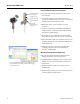
October 2014 Rosemount 5300 Series The optional Smart Wireless THUM Adapter can be mounted directly on the transmitter or by using a remote mounting kit. IEC 62591 (WirelessHART) enables access to multi-variable data and diagnostics, and adds wireless to almost any measurement point.
October 2014 Rosemount 5300 Series Maximum load resistance is determined by the voltage level of the external power supply, as described by: Non-Hazardous Installations R( 1400 Maximum Load Resistance 1387 1200 1000 800 600 Operating Region 586 400 200 External Power Supply Voltage 24 10 16 20 42.
October 2014 Rosemount 5300 Series FOUNDATION™ fieldbus (output option code F) - (see signal output in Table 1 on page 5 and Table 2 on page 15) FOUNDATION fieldbus Host / DCS system (e.g.
October 2014 Rosemount 5300 Series Modbus (Output option code M) - (see signal output in Table 1 on page 5 and Table 2 on page 15) The RS-485 Modbus version communicates by Modbus RTU, Modbus ASCII, and Levelmaster protocols. 8 data bits, 1 start bit, 1 stop bit, and software selectable parity. Baud Rate: 1200, 2400, 4800, 9600 (default), and 19200 bits/s. Address Range: 1 to 255 (default device address is 246).
October 2014 Rosemount 5300 Series Display and configuration Integral Display (option code M1) The integral digital display can toggle between: level, distance, volume, internal temperature, interface distance, interface level, peak amplitudes, interface thickness, percentage of range, analog current out Note The display cannot be used for configuration purposes.
October 2014 Rosemount 5300 Series Diagnostics General Transmitter diagnostics with alerts include hardware and software errors, electronics temperature, probe missing, and invalid measurement and configuration error diagnostics. In addition to this, echo curve and variable logging including signal strength facilitate easy on-line troubleshooting. Diagnostics Suite (option code D01 or DA1) Signal Quality Metrics - Diagnostics package that monitors the relations between surface, noise and threshold.
October 2014 Rosemount 5300 Series Temperature and pressure limits The maximum and minimum ambient temperature for the electronics depends on the process temperature (as described by the graph below) and on the approval (see “Product Certifications” on page 55).
October 2014 Rosemount 5300 Series Note The flanges, except the Fisher and Masoneilan flanges, are triple certified for the materials 316, 316L, and EN 1.4404. The pressure rating is according to 316L. Max.
October 2014 Rosemount 5300 Series Max. Rating, Cryogenic Temperature Tank connections (Operating Temperature and Pressure code C) Pressure psig (bar) Process Temperature (continued) -320 (-196) -200 (-129) Temperature °F (°C) Final rating may be lower depending on flange selection. 316L SST flanges according to ASME B16.5 Table 2-2.3: Standard: Max.
October 2014 Tri-Clamp Rating Rosemount 5300 Series Maximum pressure is 16 bar for 1½-in. (37.5 mm) and 2-in. (50 mm) housing; and 10 bar for 3-in. (75 mm) and 4-in. (100 mm) housing. The final rating depends on the clamp and gasket. Tri-Clamp is available for the Standard Temperature and Pressure seal. Certain models of flanged alloy and PTFE covered probes have a tank connection design with a protective flange plate of the same material as the probe and with a backing flange in 316L / EN 1.4404.
October 2014 Rosemount 5300 Series Interface measurements The Rosemount 5302 is a good choice for measuring the interface of oil and water, or other liquids with significant dielectric differences. It is also possible to measure interfaces with a Rosemount 5301 in applications where the probe is fully submerged in the liquid.
October 2014 Rosemount 5300 Series Solids measurements Rosemount 5303 with a flexible single lead probe is a good choice for measuring solids, such as powders, granulates, or pellets with a grain size of up to 0.8 in. (20 mm). The measurement is made where the probe comes in contact with the material, which means that the shape of the material surface is not critical for the measurement. Measurements are also independent of moisture and material fluctuations such as density and temperature.
October 2014 Rosemount 5300 Series High pressure steam applications Saturated steam under high pressure can influence radar level transmitter measurements. Rosemount 5301 with Dynamic Vapor Compensation will automatically compensate for this and maintain the level accuracy. Probe type 3V (for 3- to 4-in. chambers) or 4U (for 2-in. chambers) must be used. Mount in a 2-, 3-, or 4-in. bypass chamber with flanges appropriately sized for the pressure and temperature of the application.
October 2014 Select Reference Reflector Rosemount 5300 Series The long reflector, 20 in. (500 mm), has the best accuracy and is recommended for all chambers where the dimensions of the chamber allow for it. If the distance from the flange to the upper inlet is less than 28 in. (710 mm), the short reflector should be chosen. This distance is a minimum when dynamic compensation is required within the whole measuring range from the lower to the upper inlet.
October 2014 Rosemount 5300 Series Table 4. Temperature Ranges for Standard Tank Seals with Different O-ring Materials Tank seal with different o-ring material Min. temperature °F (°C) in air Max. temperature °F (°C) in air Viton® Fluoroelastomer 5 (-15) 302 (150) Ethylene Propylene (EPDM) -40 (-40) 266 (130) Kalrez® 6375 Perfluoroelastomer 14 (-10) 302 (150) Nitrile Butadiene (NBR) -31 (-35) 230 (110) Note Always check the chemical compatibility of the o-ring material with your application.
October 2014 Rosemount 5300 Series Performance specifications General Reference Conditions Single Standard probe, 77°F (25°C) in water (DC=80) and ambient pressure in a 4” pipe using Trim Near Zone function. Reference Accuracy ± 0.12 in. (3 mm) or 0.03% of measured distance, whichever is greatest(1) Repeatability ± 0.04 in. (1 mm) Ambient Temperature Effect ± 0.008 in. (0.
October 2014 Rosemount 5300 Series Measuring range 16 in. (0.4 m) to 164 ft (50 m) See Table 8 on page 44 for each probe’s measuring range and minimum dielectric constant. Due to the measuring range depending on the application and factors described below, the values are a guideline for clean liquids. For more information, ask your local Emerson Process Management representative.
October 2014 Rosemount 5300 Series Target applications include interfaces between oil / oil-like and water / water-like liquids with a low (<3) dielectric constant for the upper product and a high (>20) dielectric constant for the lower product. For such applications, the maximum measuring range is limited by the length of the coaxial, rigid twin, and rigid single lead probes.
October 2014 Rosemount 5300 Series Accuracy over measuring range The measuring range depends on probe type, dielectric constant of the product and installation environment, and is limited by the Blind Zones at the very top and bottom of the probe. In the Blind Zones, the accuracy exceeds ±1.18 in. (30 mm), and measurements may not be possible. Measurements close to the Blind Zones will have reduced accuracy.
October 2014 Rosemount 5300 Series Figure 2. Accuracy Over Measuring Range for Coaxial Probe Water (DC = 80) Oil (DC = 2) ±0.12 in. ±1.18 in. ±0.12 in. ±1.18 in. (3 mm) (30 mm) (3 mm) (30 mm) Accuracy 2 in. (5 cm) Accuracy 3.5 in. (9 cm) 7 in. (18 cm) 7.5 in. (19 cm) Blind Zone 0.8 in. (2 cm) 5.1 in. (13 cm) Figure 3. Accuracy Over Measuring Range for Twin Lead Probes Water (DC = 80) Oil (DC = 2) ±0.12 in. ±1.18 in. ±0.12 in. ±1.18 in. (3 mm) (30 mm) (3 mm) (30 mm) Accuracy 3.
October 2014 Rosemount 5300 Series Table 8. Measuring Range and Minimum Dielectric Constant Rigid single lead/ segmented rigid single lead Flexible single lead(1) Coaxial Rigid twin Lead Flexible twin lead 164 ft (50 m) 19 ft 8 in. (6 m) 9 ft 10 in. (3 m) 164 ft (50 m) 1.4 (Std) (Std) 1.4, up to 82 ft (25 m)(1) 2.0, up to 115 ft (35 m)(1) 2.5, up to 131 ft (40 m)(1) 3.5, up to 148 ft (45 m) 6, up to 164 ft (50 m) 9 ft. 10 in. (3 m) for 8 mm probes (code 4A) Maximum measuring range 19 ft. 8 in.
October 2014 Rosemount 5300 Series Table 9.
October 2014 Rosemount 5300 Series Physical specifications Material selection Material selection Emerson provides a variety of Rosemount product with various product options and configurations including materials of construction that can be expected to perform well in a wide range of applications. The Rosemount product information presented is intended as a guide for the purchaser to make an appropriate selection for the application.
October 2014 Rosemount 5300 Series Flange Dimensions Follows ASME B 16.5, JIS B2220, and EN 1092-1 standards for blind flanges. For Proprietary Fisher® and Masoneilan® flanges, see “Special flanges and flushing connection rings” on page 77 Vented Flanges Available with Masoneilan and Fisher vented flanges. Vented flanges must be ordered as accessories with a 1½-in. NPT threaded process connection (code RA); see “Special flanges and flushing connection rings” on page 77.
October 2014 Rosemount 5300 Series This is defined from the upper reference point to the end of the probe (weight included, if applicable). NPT BSP/G Flange Tri-Clamp Upper Reference Point Total Probe Length Total Probe Length Select the probe length according to the required measuring range (the probe must be hung and fully extended through the entire distance where level readings are desired). Most of the probes can be cut in field.
October 2014 Rosemount 5300 Series Long Stud (9.8 in./250 mm). When using single flexible probes in tall and narrow nozzles, a Long Stud (LS option) is recommended to prevent the probe from contacting the nozzle. Nozzle height Nozzle Considerations (see Table 11 on page 52) Nozzle diameter Make sure the nozzle does not extend into the tank. Clearance to tank wall Minimum Clearance (See Table 12 on page 53) Avoid direct contact www.rosemount.
October 2014 Rosemount 5300 Series To get best possible performance, the following must be considered before installing the transmitter: Other Mechanical Considerations Inlets should be kept at a distance in order to avoid product filling on the probe Avoid physical contact between probes and agitators, as well as applications with strong fluid movement unless the probe is anchored Probe tie-down is recommended if the probe can move to within 1 ft.
October 2014 Rosemount 5300 Series Chamber / pipe installations Side-and-Bottom dimension The probe length to use for a Rosemount 9901 chamber can be calculated by using Table 13 on page 53. Use a centering disc if the probe length >3.3 ft (1 m). See “Probe Type in Chamber Considerations” on page 52 and “Centering Discs” on page 52 for which probe and disc to use.
October 2014 Rosemount 5300 Series When installing a Rosemount 5300 in a chamber, the single lead probe is recommended. An exception is with liquefied gas > 40 bar where the coaxial probe is recommended. The recommended minimum chamber diameter is 4 in. (100 mm) for Single Flexible probe and 3 in. (75 mm) for the Single Rigid probe. The probe should be centered to prevent it touching the sides of the well.
October 2014 Rosemount 5300 Series Table 12. Minimum Clearance Rigid single lead/ Flexible single lead segmented rigid single lead Min. clearance to tank wall (L) or obstruction(1) Coaxial 4 in. (10 cm) if smooth metallic wall. 4 in. (10 cm) if 0 in. (0 cm) smooth metallic wall. 20 in. (50 cm) if disturbing objects, rugged metallic or concrete/plastic wall. 20 in. (50 cm) if disturbing objects, rugged metallic or concrete/plastic wall. Min. chamber/ 2 in.
October 2014 Rosemount 5300 Series Table 15. Centering Disc Dimensions Disc size Actual disc diameter 2 in. 1.8 in. (45 mm) 3 in. 2.7 in. (68 mm) 4 in. 3.6 in. (92 mm) 6 in. 5.55 in. (141 mm) 8 in. 7.40 in. (188 mm) Table 16. Centering Disc Size Recommendation for Different Pipe Schedules Pipe size Pipe schedule 5s, 5 10s, 10 40s, 40 80s, 80 120 2 in. 2 in. 2 in. 2 in. 2 in. NA(1) NA(2) 3 in. 3 in. 3 in. 3 in. 3 in. NA(1) 2 in. 4 in. 4 in. 4 in. 4 in. 4 in. 4 in. 3 in.
October 2014 Rosemount 5300 Series Product Certifications EU conformity The most recent revision of the EC declaration of conformity can be found at www.rosemount.com. Safety Instrumented Systems (SIS) Temp. Code T4 Ambient temperature limits: -50 °C to +70 °C(1) Approval valid for HART, FOUNDATION fieldbus, and FISCO options.
October 2014 Rosemount 5300 Series E6 Explosion-proof with internal intrinsically safe circuits [Exia] Class I, Div. 1, Groups B, C, and D; Class II, Div. 1 and 2, Groups E, F, and G; Class III, Div. 1 Temp Code T4. Ambient temperature limits -50 °C to +70 °C(1) WARNING: The substitution of components may impair intrinsic safety. Approval valid for HART, FOUNDATION fieldbus, and Modbus options. 4.
October 2014 EAC certifications Rosemount 5300 Series E2 4-20 mA/HART model: Ex d ia IIC T4 Gb/Ga Ex ta IIIC T79 °C -40 °C
October 2014 Rosemount 5300 Series Chinese certifications Japanese certifications National Supervision and Inspection Center for Explosion Protection and Safety of Instrumentation (NEPSI) approvals Technology Institution of Industrial Safety (TIIS) approval Special Conditions for Safe Use (X): Refer to Certificates GYJ 111230X and GYJ 13.1387.
October 2014 IECEx certifications Rosemount 5300 Series I7, IG Intrinsically safe and FISCO model: Certificate: IECEx NEM 06.0001X IECEx approvals Ex ia IIC T4 Ga (-50 °C < Ta < +70 °C(1)) Ex ia/ib IIC T4 Ga/Gb(3) Ex ta IIIC T 79 °C(2) Da (-50 °C < Ta < +70 °C(1)) 4-20 mA/HART model: Ui = 30 Vdc, Ii = 130 mA, Pi = 1.0 W, Ci = 7.26 nF, Li = 0 H. FOUNDATION fieldbus model: Ui = 30 Vdc, Ii = 300 mA, Pi = 1.5 W, Ci = 4.95 nF, Li = 0 H. FISCO model: Ui = 17.5 Vdc, Ii = 380 mA, Pi = 5.32 W, Ci = 4.
Rosemount 5300 Series October 2014 Other certifications U1 Overfill protection Certificate: Z-65.16-476 TÜV-tested and approved by DIBt for overfill protection according to the German WHG regulations Approval valid for HART and FOUNDATION fieldbus options. Suitability for intended use Compliant with NAMUR NE 95, version 07.07.
October 2014 Rosemount 5300 Series Dimensional Drawings Figure 4. Rigid Single Lead Probe with Flange Connection Dimensions are in inches (millimeters). 7.1 (180) 3.4 (87) 3.6 (92) PTFE covered probe and protective plate ½ - 14 NPT Optional adapters: M20x1.5, eurofast and minifast 5.2 (133) 7.4 (188.5) 10.1 (257.5) Alloy probe and protective plate The PTFE and Alloy probes are designed with a protective plate L 10 ft (3 m) for Ø 0.31 (8) L 20 ft (6 m) for Ø 0.51 (13) Ø 0.31 (8) or 0.
October 2014 Rosemount 5300 Series Figure 5. Rigid Single Lead Probe with Tri-Clamp Connection Dimensions are in inches (millimeters). 7.1 (180) 3.4 (87) 3.6 (92) ½ - 14 NPT Optional adapters: M20x1.5, eurofast and minifast 5.2 (133) 7.4 (188.5) 10.1 (257.5) L 10 ft (3 m) for Ø 0.31 (8) L 20 ft (6 m) for Ø 0.51 (13) Ø 0.31 (8) or 0.51 (13): SST probe Ø 0.47 (12): PTFE covered probe 10.1 (257.5) PTFE covered probe and protective plate 62 www.rosemount.
October 2014 Rosemount 5300 Series Figure 6. Rigid Single Lead Probe with Threaded Connection Dimensions are in inches (millimeters). NPT 1/1½/2 inch 7.1 (180) NPT 1/1½/2 inch 5.2 (133) ½ - 14 NPT Optional adapters: M20x1.5, eurofast and minifast 3.4 (87) 3.6 (92) 7.4 (188.5) 10.1 (257.5) 2.4 (62) 1 in. / 1½ in.: s52 2 in.: s60 L 10 ft (3 m) for Ø 0.31 (8) L 20 ft (6 m) for Ø 0.51 (13) Ø 0.31 (8) or 0.51 (13): SST probe Ø 0.47 (12): PTFE covered probe G 1/1½ inch NPT 1½, G 1½ inch 7.
October 2014 Rosemount 5300 Series Figure 7. Segmented Rigid Single Lead Probe with Flange Connection Dimensions are in inches (millimeters). 5.2 (133) 7.1 (180) HTHP/HP/C version 3.4 (87) 3.6 (92) ½ - 14 NPT Optional adapters: M20x1.5, eurofast and minifast 7.4 (188.5) 10.1 (257.5) 15.6 (397.5) 0.6 (15) 15.2 (385) 55 (2.2) 15.2 (385) 31.5 (800) L 33 ft (10 m) Optional: PTFE centering disc Optional: Bottom centering disc (SST or PTFE) Ø 0.51 (13) 64 www.rosemount.
October 2014 Rosemount 5300 Series Figure 8. Segmented Rigid Single Lead Probe with Threaded Connection Dimensions are in inches (millimeters). 5.2 (133) 7.1 (180) 3.4 (87) 3.6 (92) ½ - 14 NPT Optional adapters: M20x1.5, eurofast and minifast 7.4 (188.5) 10.1 (257.5) NPT 1 in., s52 NPT 1½ in., s52 NPT 2 in., s60 15.2 (385) BSP-G 1 in., s52 BSP-G 1½ in., s60 1.1 (27) 2.4 (62) 2.4 (62) 0.6 (15) 31.5 (800) HTHP/HP/C version L 33 ft (10 m) Optional: PTFE centering disc NPT 1½ in.
October 2014 Rosemount 5300 Series Figure 9. Single Rigid Vapor Probe for 2-in. Chambers Dimensions are in inches (millimeters). 7.1 (180) 3.4 (87) 3.6 (92) 5.2 (133) ½ - 14 NPT Optional adapters: M20x1.5, eurofast and minifast W/O housing 16 (397) Upper reference point Ø 0.5 (13) Chamber flange BSP-G 1½ in., s60 NPT 1½ in., s50 9 (226) 4.3 (109) Thread sealing 1.1 (27) Short reflector: 13.8 (350) Long reflector: 19.7 (500) Chamber/pipe (metal) L 7.5 ft (2.3 m) Water surface Minimum 8.3 in.
October 2014 Rosemount 5300 Series Figure 10. Flexible Single Lead Probe with Flange Connection Dimensions are in inches (millimeters). 7.1 (180) 5.2 (133) 3.4 (87) 3.6 (92) ½ - 14 NPT Optional adapters: eurofast and minifast 7.4 (188.5) 10.1 (257.5) Short weight (option W2) 2 (50): 4 mm SST probe Ø 1.5 (37.5): 4 mm SST probe Ø 0.16 (4): SST probe Ø 0.24 (6): SST probe Ø 0.28 (7): PTFE covered probe L 164 ft (50 m) The PTFE covered probe is designed with a protective plate.
October 2014 Rosemount 5300 Series Figure 11. Flexible Single Lead Probe with Tri-Clamp Connection Dimensions are in inches (millimeters). 5.2 (133) 7.1 (180) 3.4 (87) 3.6 (92) ½ - 14 NPT Optional adapters: eurofast and minifast 7.4 (188.5) 10.1 (257.5) Short weight (option W2) 2 (50): 4 mm SST probe Ø 1.5 (37.5): 4 mm SST probe L 164 ft (50 m) Ø 0.16 (4): SST probe Ø 0.24 (6): SST probe Ø 0.28 (7): PTFE covered probe 5.5 (140): 4 and 6 mm SST probes 17.1 (434): PTFE covered probe Ø 0.
October 2014 Rosemount 5300 Series Figure 12. Flexible Single Lead Probe with Threaded Connection Dimensions are in inches (millimeters). NPT 1/1½/2 inch 7.1 (180) 3.4 (87) 3.6 (92) NPT 1/1½/2 inch 5.2 (133) ½ - 14 NPT Optional adapters: M20x1.5, eurofast and minifast 7.4 (188.5) Short weight (option W2) 10.1 (257.5) 2.4 (62) 2 (50): 4 mm SST probe 1 in. / 1½ in.: s52 2 in.: s60 Ø 1.5 (37.5): 4 mm SST probe Heavy weight (option W3) L 164 ft (50 m) 5.5 (140): 4 and 6 mm SST probes 17.
October 2014 Rosemount 5300 Series Figure 13. Coaxial Probe with Flange Connection Dimensions are in inches (millimeters). 7.1 (180) 3.4 (87) 3.6 (92) 5.2 (133) ½ - 14 NPT Optional adapters: M20x1.5, eurofast and minifast 7.4 (188.5) 10.1 (257.1) The Alloy probes are designed with a protective plate L 20 ft (6 m) 1.1 (28) HTHP/HP/C version 15.6 (397.5) 70 HTHP/HP Plate Design (Option for Alloy versions) 15.6 (397.5) www.rosemount.
October 2014 Rosemount 5300 Series Figure 14. Coaxial Probe with Threaded Connection Dimensions are in inches (millimeters). NPT 1/1½/2 inch NPT 1/1½/2 inch 7.1 (180) 5.2 (133) ½ - 14 NPT Optional adapters: M20x1.5, eurofast and minifast 3.4 (87) 3.6 (92) 7.4 (188.5) 10.1 (257.1) 2.4 (62) 1 in., 1½ in.: s52 2 in.: s60 L 20 ft (6 m) 1.1 (28) G 1/1½ inch NPT 1½, G 1½ inch 7.1 (180) HTHP/HP/C version 3.4 (87) 3.6 (92) 10.1 (257.1) 15.6 (397.5) 1 in.: s52 1½ in.: s60 1.
October 2014 Rosemount 5300 Series Figure 15. Integrated Still Pipe Vapor Probe for 3-in. Chambers and above Dimensions are in inches (millimeters). 7.1 (180) 3.4 (87) 3.6 (92) ½ - 14 NPT Optional adapters: M20x1.5, eurofast and minifast 5.2 (133) 7.4 (188.5) 16 (397) Upper reference point Ø 1.1 (28) L 13 ft. 1 in. (4 m) Water surface Tank flange Short reflector: 13.8 (350) Long reflector: 19.7 (500) Minimum 8.3 in.
October 2014 Rosemount 5300 Series Figure 16. Rigid Twin Lead Probe Dimensions are in inches (millimeters). G 1½ inch 7.1 (180) 3.4 (87) 3.6 (92) ½ - 14 NPT Optional adapters: M20x1.5, eurofast and minifast NPT 1½ / 2 inch NPT 1½ / 2 inch 7.1 (180) 5.2 (133) 3.4 (87) 3.6 (92) 7.4 (188.5) 10.2 (259.5) 10.2 (259.5) s60 1.8 (45) 1.1 (27) L 10 feet (3 m) 1½ in.: s52 2 in.: s60 L 10 feet (3 m) Ø 0.24 (6) Ø 0.24 (6) Ø 0.31 (8) Ø 0.31 (8) 1.0 (26) 1.0 (26) Flange Flange 7.1 (180) 5.
October 2014 Rosemount 5300 Series Figure 17. Flexible Twin Lead Probe Dimensions are in inches (millimeters). G 1½ inch 7.1 (180) 3.4 (87) 3.6 (92) ½ - 14 NPT Optional adapters: M20x1.5, eurofast and minifast NPT 1½ / 2 inch NPT 1½ / 2 inch 7.1 (180) 5.2 (133) 3.4 (87) 3.6 (92) 7.4 (188.5) 10.2 (259.5) 10.2 (259.5) s60 1.8 (45) 1.1 (27) L 164 feet (50 m) Ø 0.16 (4) L 164 feet (50 m) 1½ in.: s52 2 in.: s60 Ø 0.16 (4) Ø 0.16 (4) Ø 0.16 (4) 3.5 (90) 3.5 (90) 1.4 (35) 1.
October 2014 Rosemount 5300 Series Figure 18. Mounting Bracket (Option Code BR) Dimensions are in inches (millimeters). Pipe diameter max 2.5 in. (64 mm) 5.2 (133) Pipe mounting (vertical pipe) Pipe mounting (horizontal pipe) 2.2 (57) 0.3 (7) 2.8 (70) 0.8 (20) Wall mounting www.rosemount.
October 2014 Rosemount 5300 Series Figure 19. Remote Housing (Option Code B1, B2, B3) Dimensions are in inches (millimeters). 7 (180) 5.2 (133) 3.4 (87) 3.6 (92) 7.4 (188.5) 5.2 (133) 3, 6, 9 ft. (1, 2, or 3 m) Hmin: 6.9 (175) Standard Variant 12.4 (315) HTHP/HP/C Variant 76 Rmin 1.4 (35) www.rosemount.
October 2014 Rosemount 5300 Series Special flanges and flushing connection rings Raised Face Recessed Face B1 B1 Dimensions are in inches (millimeters). D: Outside diameter B1: Flange thickness with gasket surface # B2: Flange thickness without gasket surface G K D G K D F=B1-B2: Gasket surface thickness G: Gasket surface diameter # Bolts: Number of bolts K: Bolt hole circle diameter B2 B2 Note Dimensions may be used to aid in the identification of installed flanges.
Rosemount 5300 Series Product Data Sheet 00813-0100-4530, Rev FA October 2014 Emerson Process Management Rosemount Inc. 8200 Market Boulevard Chanhassen, MN 55317 USA T (U.S.) 1-800-999-9307 T (International) (952) 906-8888 F (952) 906-8889 www.rosemount.com Emerson FZE P.O. Box 17033 Jebel Ali Free Zone Dubai UAE Tel +971 4 811 8100 Fax +971 4 886 5465 www.rosemount.com Emerson Process Management Latin America 1300 Concord Terrace, Suite 400 Sunrise Florida 33323 USA Tel +1 954 846 5030 www.