
Wall Docking Station Operation/Reference Guide


MVP-WDS Wall Docking Station & CB-MVPWDS Conduit Box
24
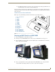
MVP-WDS Wall Docking Station for MVP Panels
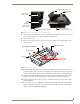
Open the Battery Compartment by pressing down on the Battery Compartment Latch and then
pulling the cover outwards.
Press the Cradle Activation pushbutton (the small recessed white button located near the pins
in Battery Slot #2) to make the MVP Support Cradle rise upwards. The MVP Support Cradle
must be angled upward to allow removal of the faceplate.
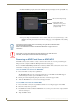
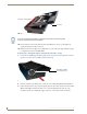
Disconnect the 2-pin mini-Phoenix connector from the side of the docking station to remove
power from the unit. Removing power from the MVP-WDS at this point maintains the support
cradle in this angled position.
5. Slide the silver Faceplate over the angled Support Cradle, toward the Security Release Pushbutton’s
circuit board on the MVP-WDS.
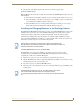
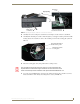
6. Gently press the silver faceplate down and under the Security Latch until it rests against the
Mounting Tabs of the MVP-WDS main unit.
Be sure to snap the Faceplate Connectors into their respective Latches (located along the
bottom rim of the faceplate - see FIG. 20 on page 20).
Verify that the two faceplate security screw holes on both the Faceplate and the main
MVP-WDS unit are properly aligned.
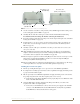
7. Insert and secure the two #6-32 Faceplate Security Screws into the top rim of the Faceplate using a
screwdriver.
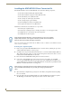
8. Apply power to the MVP-WDS by connecting the terminal end of the power cable to the power
supply.
9. Press the Cradle Activation pushbutton to cause the MVP Support Cradle to angle backwards and
lie flush against the main unit.
10. Remove the two adhesive plastic Die Cut Foam covers (60-5965-47) from the strip included within
the Installation Kit bag.
11. Adhere these two plastic Die Cut Foam covers into the two notches where the #6-32 Faceplate
Security Screws are located (FIG. 18 on page 19).
12. Reapply power to the unit.
Refer to the Connecting a Power Supply section on page 13 for more information.
13. Install the WDS back into its previous location.
Refer to the Installation section on page 4 for more information.