
Wall Docking Station Operation/Reference Guide


MVP-WDS Wall Docking Station & CB-MVPWDS Conduit Box
23
MVP-WDS Wall Docking Station for MVP Panels
5. Use the screwdriver to install one of the previously removed MVP Support Cradle Securing screws
to the securing plate (shown in FIG. 23 on page 21).
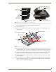
6. Carefully slide the entire silver battery pivot combo unit into the black WDS metal housing.
Be careful not to knock or damage the interface connector pin circuit board.
7. Insert the screwdriver (with attached securing screw) into the large hole along the side of the WDS
housing (shown in FIG. 22 on page 21).
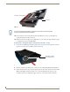
8. Position the unit so you can get a better view and orient the position of this screw back into its
location where it secures the support cradle to its associated movement mechanism (shown in
FIG. 22 on page 21).
9. Carefully secure the cradle pivot’s attachment screw. This procedure limits the movement of the
silver pivot combo unit.
10. Align the MVP Support Cradle Securing plate (FIG. 21 on page 20) to its corresponding holes
along the outside of the housing and screw in the remaining two MVP Support Cradle Securing
screws back to the lower right side of the unit (FIG. 21 on page 20).
11. Place the magnetic cup into the circular Securing Magnet location and secure it to the pivot combo
unit by using a grounded flat-head Phillips screwdriver to screw in the single #4-20 Magnet
Securing screw (80-0193-01) through the cup.
12. Place the small circular rare earth magnet (68-5965-02) into the secured magnetic cup. The charge
on the magnet allows it to stay in place and remain flush against the magnetic cup.
Installing the new silver faceplate
1.
Turn the pre-existing black faceplate over to expose the rear of the illuminated pushbutton.
2. In a single motion carefully squeeze both sides of the rear pushbutton and apply downward pressure
to pop it out from the black faceplate.
3. Take the previously removed illuminated pushbutton and apply downward pressure to insert it into
the opening along the bottom of the silver faceplate (until you hear a click).
Verify that the Security Release Pushbutton is now properly aligned over it’s LEDs and circuit
board on the MVP-WDS main unit.
4. Verify the MVP Support Cradle is angled upwards. This position allows you to slide on the
faceplate. If the cradle is not angled upwards:
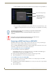
Connect the 3.5 mm mini-Phoenix connector from an active power supply to the side PWR
connector on the MVP-WDS. The two blue LEDs behind the Security Release pushbutton
should illuminate to indicate that the unit is receiving power.
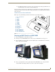
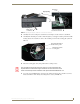
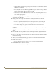
FIG. 25 Installation of silver cradle pivot and battery cover
Silver battery cover
Pivot combo unit
Silver cradle pivot
(battery cover and pivot)
Battery cover guide
(60-5965-21L)
(60-5965-22SL)