Operation/Reference Guide ViewStat Communicating Thermostat P r od u c t C a t e g o r y L as t R e vi s ed: 5 /1 6 /20 0 8
AMX Limited Warranty and Disclaimer AMX Corporation warrants its products to be free of defects in material and workmanship under normal use for three (3) years from the date of purchase from AMX Corporation, with the following exceptions: • Electroluminescent and LCD Control Panels are warranted for three (3) years, except for the display and touch overlay components that are warranted for a period of one (1) year.
Table of Contents Table of Contents Product Information ...........................................................................................1 Introduction .............................................................................................................. 1 System Components ................................................................................................. 2 ViewStat Specifications.............................................................................................
Table of Contents Address the Thermostats and Set Highest Address................................................ 24 Wiring Diagrams ..................................................................................................... 26 Single-stage furnace and AC configuration. .................................................................. 26 Two-stage furnace and two-stage AC configuration. ....................................................
Table of Contents Operating the Thermostat ................................................................................57 Front Panel Components ........................................................................................ 57 Message Display ........................................................................................................... 57 Scroll/Set-up buttons .................................................................................................... 57 Mode button .....
Table of Contents iv ViewStat Communicating Thermostat
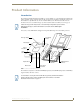
Product Information Product Information Introduction The ViewStat Communicating Thermostat (FIG. 1) operates similarly to a conventional thermostat but has the unique capability of being controlled, either locally or remotely from a NetLinx or Landmark control system. The ViewStat is compatible with any 24-volt controlled HVAC system. This manual describes how the ViewStat connects to several different types (see theViewStat Installation and Wiring section on page 7).
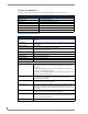
Product Information System Components The components in a complete ViewStat system (including optional accessories) are listed below: System Components Component Name Description ViewStat (VST) Communicating thermostat VST-TTM Temperature support module (optional) VST-TRH Temperature/Humidity support module (optional) VST-TSF Flush-mount remote sensor Indoor flush-mount temperature/relative humidity sensor (optional) VST-TSO Duct/Outdoor remote sensor Duct/Outdoor-mount temperature/relative humid
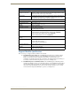
Product Information ViewStat Specifications (Cont.) Circuit Board Components: Communication and HVAC Terminals with captive-wire connectors that connects the Thermostat, HVAC Equipment connectors equipment, control system, remote sensors and power supply. Refer to the Wiring the Thermostat section on page 20 for details. DIP Switch 4-position DIP switch that configures the thermostat for various application types (Servant/Master, Electric/Fossil, Single/Multi, Heat Pump/Heat-Cool).
Product Information The ViewStat supports up to four Support Modules, and can display any one of the following: The remote temperature on support module address 1 if its mode is set to "Control". The average temperatures of all support modules set to "Control" mode. The humidity of the VST-TRH (Temperature and Humidity Module) set to "Control" mode. VST-TTM and VST-TRH Remote Sensor Specifications Power supply 18 to 30 VAC or DC (24 V Nominal) Support Module Dimensions (HWD) 2.50" x 3.50" x 0.
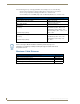
Product Information HVAC System Pre-Installation Check List Before getting started, determine what type of heating system is/will be installed in the house. Then use the following table to determine if the proper numbers of wires are available, depending on the HVAC System type. HVAC System Pre-installation Check List Application # of HVAC Wires Wiring Diagram Single Stage Furnace & AC 5 FIG. 18 on page 26 Two Stage Furnace & Two Stage AC 7 FIG.
Product Information 6 ViewStat Communicating Thermostat
ViewStat Installation and Wiring ViewStat Installation and Wiring This section covers the installation, wiring and checkout of a ViewStat Communicating Thermostat System. 1. 120 volts may cause serious injury from electrical shock. Disconnect electrical power to the HVAC system before starting installation. This system is a low-voltage system. 2. Improper installation may cause serious injury from electrical shock.
ViewStat Installation and Wiring Removing the Faceplate from the Base No tools are required to disassemble the thermostat – just use your hands to pull the front panel off of the base (FIG. 2). FIG. 2 Pulling the front panel off of the base Loss of internal programs may result from static discharge to thermostat circuit board. Touch a grounded metal object to discharge any static charge before handling the circuit board.
ViewStat Installation and Wiring Setting the DIP Switch FOSSIL MULTI SINGLE HT.PUMP OFF ON H/C MASTER SERVANT ELECTRIC Set the DIP switch located on the thermostat circuit board (FIG. 4) according to the application needs (see the DIP Switch Settings table below for details). FIG. 4 Setting the DIP Switch The following table shows what each switch corresponds to depending on position.
ViewStat Installation and Wiring Attaching the MiniVerter to the ViewStat Before attaching the MiniVerter to the rear of the ViewStat, connect the wiring, as described below: 1. Detach the faceplate from the base of the ViewStat. 2. Pull the stripped/tinned wires through the cutout in the center of the base (FIG. 5). Common (black) from 24 VAC HVAC System Power Terminal Power (red) from 24 VAC HVAC System cutout jumper from RC to RH Communication Terminal Equipment terminal from Miniverter FIG.
ViewStat Installation and Wiring ViewStat base (top view) 1 Insert the MiniVerter (connector-side down) into the guide slots inside the mounting bracket. MiniVerter card 2 MiniVerter mounting bracket 3 Slide the MiniVerter into locking position in the bracket. Snap into place FIG. 6 Inserting the MiniVerter into the mounting bracket (top view). Repeated installation and removal of the MiniVerter bracket may result in damage to the bracket. 9.
ViewStat Installation and Wiring Rx+ RxTx+ Tx- 24VAC GND Switches 3 A - Allows Transmit Communications B - Allows Received Communications PWR - Turns power to thermostat on/off Communications Wire to Protocol Adapter, other Distribution Panels or directly to Automation System A: Transmit B: Receive 2 REF LEDs light when communications are transmitted (A) or received (B) ADDRESS # ADDRESS # ADDRESS # ADDRESS # ADDRESS # ADDRESS # 1 ADDRESS # Transformer 24 V, 40 VA minimum up to 8 thermostats C -
ViewStat Installation and Wiring Minimize wire entry hole size and seal – drafts from inside the wall could affect temperature readings. 3. Fasten the base to the wall with the supplied screws. 4. Seal wire entry using caulk, drywall putty or insulation. Loss of internal programs may result from static discharge to thermostat circuit board. Installer must touch a grounded metal object before handling the circuit board.
ViewStat Installation and Wiring It is important that the correct pairing is observed. Transmit, Receive, and Mic need to be on twisted pairs. Splitting pairs (e.g., using a white/green wire with a blue/ white wire for transmit) will result in increased crosstalk, and may result in bus failure or noise on the intercom.
ViewStat Installation and Wiring Connecting to an Axcess Master Controller via the RS232/422/485 (DB-9) Port The table below lists the connector pins, signal types, and signal functions for RS-232/RS-422/RS- 485 DB-9 (male) connector on an Axcess Master Controller (i.e. Axcent3 or Axcent3/PRO).
ViewStat Installation and Wiring Connecting to NetLinx Integrated Controllers via the RS232/422/485 (DB-9) Port The table below lists the connector pins, signal types, and signal functions for RS-232/RS-422/RS- 485 DB-9 (male) connector on an NetLinx Integrated Controllers (i.e. NI-2000/3000/4000).
ViewStat Installation and Wiring Connecting to a NetLinx Master controller via NXC-COM card The Viewstat can connect to a NetLinx NXF Cardframe or NXI equipped with a NXC-COM Dual COM Port Control Card. The following table shows the card edge pinout information for the NXC-COM card.
ViewStat Installation and Wiring Connecting to a LandMark Control System PhastLink cables are used to connect all PhastLink-compatible devices, including keypads, dimmers, J-box IR devices, amplifiers, audio switches, etc. The table below lists the RJ-45 pinout information.
ViewStat Installation and Wiring Connecting to a Landmark Control System To connect a single ViewStat to a Landmark control system, use PhastLink cabling to connect the RJ-45 jack on the ViewStat to any available PhastLink jack on the Landmark Master (MCU). The maximum cabling distance between the ViewStat and MCU is 1,000 ft (304.8 m).
ViewStat Installation and Wiring Wiring the Thermostat 1. Strip 1/4" (0.63 cm) of insulation from each wire to be used. 2. Secure wires into the terminals on the base according to the appropriate wiring diagram, as described in the following table. Refer to the Wiring Diagrams section on page 26. Use color-coding practices (i.e. white wire to W terminal) whenever possible. • Single Stage Furnace & AC Refer to FIG. 18 on page 26 • Two Stage Furnace & Two Stage AC Refer to FIG.
ViewStat Installation and Wiring Communication and Equipment Terminal Wiring Definitions (Cont.) Equipment Terminal (Cont.
ViewStat Installation and Wiring b. FIG. 15 shows a typical heat/cool wiring schematic: OUTDOOR HEAT PUMP UNIT REV VALVE HEAT R SERVICE L C W1 REV VALVE COOL Y1 B ENSURE HVAC SYSTEM POWER IS OFF BEFORE WIRING Y2 2ND STG COMP. CAUTION! DEFROST 1ST STG COMP. O USE 18-20 GA. THERMOSTAT CABLE. NUMBER OF CONDUCTORS REQUIRED DEPENDS ON THE HVAC SYSTEM BEING CONTROLLED INDOOR BLOWER/HEAT UNIT 2ND STAGE AUX. HEAT FAN RELAY W2 1ST STAGE AUX.
ViewStat Installation and Wiring Checking HVAC System Operation Use the thermostat buttons to verify that the thermostat is controlling the equipment operation. A checkout procedure is supplied in the installation instructions supplied with thermostat. This procedure will verify only that the thermostat operates the equipment. The HVAC installer may need to connect 24VAC to the R and C terminals to check HVAC operation.
ViewStat Installation and Wiring 7. Use the up arrow button to raise the set point 3°F above room temperature. In 5-10 seconds, the first stage of heating begins and the HEAT message icon begins to flash. If there is a second stage it will begin in 4 minutes. Heat Pump Only: The message HEAT -AUX is displayed when the auxiliary heat terminal (W1) is energized. The LED on top of the thermostat will illuminate. 8. Press the Mode button until OFF appears in the Main display.
ViewStat Installation and Wiring Communications Set Up More Set Thermostat Next Address Network Address 1 to 64 No.of T-stats On the Network Set Baud Rate More Select 9600 EXIT Back FIG. 17 Setting the thermostat address Write down the address for each thermostat. 6. After the address has been selected, press the Enter button to store the address. 7. Use the Scroll Up and Scroll Down buttons to set the "Number of Stats on the Network" to the highest address that will be on the thermostat network.
ViewStat Installation and Wiring Wiring Diagrams Single-stage furnace and AC configuration. ViewStat Red (power) Black (common) (from MiniVerter) FIG.
ViewStat Installation and Wiring Two-stage furnace and two-stage AC configuration. ViewStat Red (power) Black (common) (from MiniVerter) FIG. 19 Two-stage furnace and two-stage AC configuration IMPORTANT! The B terminal is for reversing valve-heat. DO NOT connect the B terminal to the common side of the transformer.
ViewStat Installation and Wiring Roof top unit (two-stage heat and two-stage cool) configuration. ViewStat Red (power) Black (common) (from MiniVerter) FIG. 20 Roof top unit (two-stage heat and two-stage cool) configuration IMPORTANT! The B terminal is for reversing valve-heat. DO NOT connect the B terminal to the common side of the transformer.
ViewStat Installation and Wiring Boiler with AC (two transformers) configuration. ViewStat Red (power) Black (common) (from MiniVerter) FIG. 21 Boiler with AC (two transformers) configuration IMPORTANT! The B terminal is for reversing valve-heat. DO NOT connect the B terminal to the common side of the transformer.
ViewStat Installation and Wiring Single-stage heat pump configuration ViewStat Black (common) Red (power) (from MiniVerter) FIG. 22 Single-stage heat pump configuration IMPORTANT! The B terminal is for reversing valve-heat. DO NOT connect the B terminal to the common side of the transformer.
ViewStat Installation and Wiring Two-stage heat pump configuration. ViewStat Black (common) Red (power) (from MiniVerter) FIG. 23 Two-stage heat pump configuration IMPORTANT! The B terminal is for reversing valve-heat. DO NOT connect the B terminal to the common side of the transformer.
ViewStat Installation and Wiring First- stage radiant floor heat, second-stage furnace one stage of cooling configuration. ViewStat Black (common) Red (power) (from MiniVerter) FIG. 24 First-stage radiant floor heat, second-stage furnace one stage of cooling configuration IMPORTANT! The B terminal is for reversing valve-heat. DO NOT connect the B terminal to the common side of the transformer.
Support Module Installation and Wiring Support Module Installation and Wiring Follow the guidelines for placement of the support modules (as described below), and locate the ViewStat indoors where the operating range of the ViewStat (32° - 99°F/0° - 37°C) will not be violated (i.e. do not install in a cold garage or hot equipment room). Refer to the Support Module Specifications section on page 3 for more information on the modules.
Support Module Installation and Wiring Pull down FIG. 26 Removing the circuit board Cut here for access FIG. 27 For side access, cut out the side vents on the scored lines. 6. Snap the circuit board back into the sub-base by sliding the top of the board in first and then snapping down on the bottom. Check to be sure that the latch holds the board properly. 7. Strip ¼ inch of insulation from the four wires at the support module. Install the wires in the terminals labeled RSR, RSC, RSB and RSA.
Support Module Installation and Wiring ViewStat (faceplate removed) To other support modules (maximum of 4 total) VST-TTM or VST-TRH support modules VST-TSF Flush-mount Indoor remote sensor VST-TSO Duct/Outdoor remote sensor FIG. 28 Daisy-chaining VST-TTM Remote Temperature and VST-TRH Remote Temperature/Humidity support modules Always make sure that there is no power to the modules by removing the thermostat from the sub-base. 1. Remove the thermostat from the sub-base. 2.
Support Module Installation and Wiring DIP switches 1 and 2: Address (1-4) The following diagram shows how to set the top two address DIP switches. Each support module must have its own address (1-4). ADDRESS 1 ADDRESS 3 ADDRESS 2 ADDRESS 4 FIG. 31 Setting the top two address switches (switches 1 and 2) DIP switch 3: Temperature Sensor 1 Each support module has two sensors: Sensor 1 and Sensor 2. Determine whether you want the Sensor 1 input to monitor or control temperature.
Support Module Installation and Wiring The ViewStat will not display temperature or humidity (Sensor 1 or Sensor 2) values if DIP switch 6 is set to T1/T2 without wiring a sensor to the T1/T2 terminal. If a sensor is connected to the T1/T2 terminal; DIP switch 6 MUST be set to Off or an invalid temperatures will be reported to the ViewStat.
Support Module Installation and Wiring Troubleshooting Remote Sensors Thermostat has no display: Check 24 VAC supply. Check for incorrect wiring between the thermostat and support module. Incorrect wiring can damage the thermostat and transformer or blow a fuse in the equipment. Also, verify that all support modules have a unique address. Thermostat displays very high temperature or humidity: Ensure that DIP switch 6 is set properly.
Set Up and Configuration Set Up and Configuration The ViewStat has many features that can be adjusted to customize operations. Temperature Control Set Up, Balance Point Set Up and Communications Set Up, in particular, should only be adjusted with the help of a qualified service technician. When first powered up, the Message Display will scroll through the current mode status, fan status, and Heating/Cooling output status. This is referred to as Passive Display because you do not interact with it.
Set Up and Configuration Network Override Set-Up This enables or disables the Network Override feature. When Network Override has been invoked the thermostat will only respond to the buttons of the thermostat; commands sent by the automation system are ignored. Pressing the Enter button activates Network Override. However, you can disable this feature if you don’t want users to be able to activate Network Override. Enabling and Disabling of this feature is done through Thermostat Set-Up (FIG. 33).
Set Up and Configuration Security Set-Up This prevents unauthorized individuals from accessing Thermostat Set-Up. A code can be setup that must be entered to gain entry into Thermostat Set-Up (FIG. 35). Security Set Up Remove Password More Next Set New Password More Enter Lockout Code ConfirmCode #### accept change after 4th digit entered after 4th digit entered EXIT Back FIG. 35 Security set-up FIG.
Set Up and Configuration Communications Set-Up This is where the thermostat address is entered. Additionally, the total number of thermostats (or the highest addressed stat on the network) is entered here to optimize communication timing. Consult a qualified service technician before changing any of the values in this Sub-Menu (Sub-Menu not shown). Temperature Set-Up The first and second stage differentials can be changed, as can the display temperature offset.
Set Up and Configuration Backlight Set Up On With Every Change Next More On Only When Needed More Set, 1=lighter 2-darker toggle between 1 and 2 using the Up and Down buttons Disable More EXIT Back FIG. 37 Backlighting set-up Balance Point Set-Up Balance points limit heat pump operation when the outdoor temperature is too high or too low. It requires an optional support module with an outdoor temperature sensor.
Set Up and Configuration Display Set Up More Temperature Scale °F°C F Show Temp Setpts Always Next Show Setpts Only If Changed More Display Time and Date? Yes EXIT Back FIG.
Using the NetLinx Module to Program the ViewStat Using the NetLinx Module to Program the ViewStat AMX_ViewStat NetLinx Module - Overview The ViewStat Communicating Thermostat may be controlled from a NetLinx system using the AMX_ViewStat NetLinx module. This module requires ViewStats to be connected through an ICSNet interface. The ViewStat module is designed to save you the work of manually coding the entire ViewStat command set.
Using the NetLinx Module to Program the ViewStat It is important that the serial number array be the same length as the device array. If the serial number array happens to be shorter, the length will be set to that of the device array and the new members of the array will be set to the value 1.
Using the NetLinx Module to Program the ViewStat cool setpoint would be set to 72. While the temperature is within this range nothing is done. Once the temperature falls outside this range the system takes action and switches to the appropriate mode. 5. Humidify/Dehumidify: Some systems can maintain the humidity level within a certain range. These are similar to temperature setpoints except instead of temperature control equipment the system is controlling humidify and dehumidify equipment.
Using the NetLinx Module to Program the ViewStat Command Interface - SEND_COMMANDs (Cont.) Command 'T- FAN?' Description Query for current fan state. Parameter: • : id of thermostat/zone Example: 'T-2 FAN?' 'T- FMODE-' Set fan mode. Parameters: • : id of thermostat/zone • : 0 = let thermostat control the fan 1 = turn fan on T = toggle fan mode Example: 'T-12 FMODE-AUTO' 'T- FMODE?' Query for current fan mode.
Using the NetLinx Module to Program the ViewStat Command Interface - SEND_COMMANDs (Cont.) Command 'T- HMODE?' Description Query for current humidify mode. Parameter: • : id of thermostat/zone Example: 'T-22 HMODE?' 'T- HOLD-' Set thermostat hold state. Parameters: • : id of thermostat/zone • : 0 = take thermostat out of hold mode 1 = place thermostat in hold mode T = toggle hold state Example: 'T-2 HOLD-ON' 'T- HOLD?' Query for current hold state.
Using the NetLinx Module to Program the ViewStat Command Interface - SEND_COMMANDs (Cont.) Command 'T- LIGHT-' Description Control backlight on thermostat. Parameters: • : id of thermostat/zone • : 0 = off 1 = on T = toggle Example: 'T-1 LIGHT-T' 'T- LOCK-' Set thermostat lock state.
Using the NetLinx Module to Program the ViewStat Command Interface - SEND_COMMANDs (Cont.) Command Description 'T- MSG-' Displays text on thermostat window when MENU is enabled. 'T- OUTHUM?' Query for current outside humidity. Parameter: • : id of thermostat/zone Example: 'T-14 OUTHUM?' 'T- OUTTEMP?' Query for current outside temperature.
Using the NetLinx Module to Program the ViewStat Command Interface - SEND_COMMANDs (Cont.) Command 'SCALE-' Description Global command to set the temperature scale. Parameter: • : C = Celsius F = Fahrenheit (default) Example: 'SCALE-F' 'SCALE?' Query for the current temperature scale. Example: 'SCALE?' 'USEDEBUG-' Global command to enable the sending of debug data to device 0. Parameter: • : 1 = enables 0 = disables 'USEDEBUG?' Query for the current debug state.
Using the NetLinx Module to Program the ViewStat String Feedback (Cont.) String 'T- FAN-' Description Reports current fan state. Parameters: • : id of thermostat/zone • : 0 = fan is off 1 = fan is on Example: 'T-2 FAN-1' 'T- FMODE-' Reports current fan mode. Parameters: : id of thermostat/zone : ON = fan on AUTO = thermostat will control the fan Example: 'T-12 FMODE-AUTO' 'T- HEAT-' Reports current heat set point.
Using the NetLinx Module to Program the ViewStat String Feedback (Cont.) String 'T- HUMIDIFY-val>' Description Reports current humidify set point. Parameters: : id of thermostat/zone : 0-97 = humidify point (in percent) Example: 'T-6 HUMIDIFY-30' 'T- ID-' Reports identification number of thermostat. 'T- LOCK-' Reports current thermostat lock state.
Using the NetLinx Module to Program the ViewStat String Feedback (Cont.) String 'T- TEMP-' Description Reports current inside temperature. Parameters: • : id of thermostat/zone • : current inside temperature Example: 'T-4 TEMP-76' 'T- TIME-' Reports thermostat time. Parameter: • : HHMM, 1630 = (4:30 p.m.) 'T- TXT-,' Reports the text to be displayed for that message.
Using the NetLinx Module to Program the ViewStat 56 ViewStat Communicating Thermostat
Operating the Thermostat Operating the Thermostat This section describes the front panel components, and gives instructions for operating the ViewStat thermostat. FIG. 40 shows the front panel. Front Panel Components Message Display Two types of messages are displayed, Permanent and Temporary Messages. Permanent Messages are those that scroll continually during thermostat operation. Temporary (flashing) Messages are intended to catch your eye and must be reset to be removed from the display.
Operating the Thermostat Fan button The fan can be operated continuously (FAN ON) or only when there is a need to heat or cool. Enter button The Enter (or Network Override) button is used to override the home automation system, to clear temporary flashing messages on the message display and with the set-up features of the thermostat. Main display The Main display (FIG. 41) provides the mode status, temperature and system status information.
Operating the Thermostat Operating The Thermostat Notes on temperature adjustments: The COOL setting must always be a minimum of 2° (F or C) higher than the HEAT setting. The thermostat will automatically maintain the 2° difference. For example, if the Cooling set point is 75°F and one changes the Heating set point to 74°F, the thermostat will automatically change the Cooling set point to 76°F.
Operating the Thermostat – Do not set the thermostat to OFF mode during periods when freezing temperatures could occur. Setting temperatures Press the Up or Down adjust button. The setting to be changed will begin to flash. Press and hold the button to change the setting. If operating in the HEAT mode, the only temperature set point available to change is the Heat setting. When the room temperature drops below this setting the heat will come on (call for heating) to raise the temperature. EM.
Operating the Thermostat ViewStat Communicating Thermostat 61
AMX. All rights reserved. AMX and the AMX logo are registered trademarks of AMX. AMX reserves the right to alter specifications without notice at any time. ©2008 5/08 It’s Your World - Take Control™ 3000 RESEARCH DRIVE, RICHARDSON, TX 75082 USA • 800.222.0193 • 469.624.8000 • 469-624-7153 fax • 800.932.6993 technical support • www.amx.