
Operating instructions

AMX Corporation reserves the right to alter specifications without notice at any time.
For full warranty information, refer to the AMX Instruction Manual(s) associated with your Product(s).
036-004-2666 10/04 ©2004
AMX Corporation. All rights reserved. The AMX logo is a trademark of AMX Corporation. AMX reserves the right to alter specifications without notice at any time.
3000 RESEARCH DRIVE, RICHARDSON, TX 75082 • 800.222.0193 • fax 469.624.7153 • technical support 800.932.6993 • www.amx.com
93-5963
REV: C
2. Connect the DB-9 end of the programming cable to the female DB-9
connector on the DB-9 extension cable (FG10-727).
3. Connect the female DB-9 terminal end of the extension cable to the port
on the back of your computer (FIG. 2) and configure the communication
parameters in TPDesign3.
Refer to the TPDesign3 Instruction Manual for details on performing file transfer
operations.
VPA-DS ViewPort Docking Station (Optional Accessory)
The ViewPort Docking Station includes a built-in battery charger and an angled
desktop docking station to cradle your ViewPoint touch panel.
Recharging the Battery
Units are shipped with batteries needing to be charged. The battery
(VPA-BP) can be recharged by connecting the 12 VDC power supply to the
power jack on the side of the ViewPoint (FIG. 1). The battery can also be
charged on the optional ViewPort docking station (VPA-DS).
Power to charge the battery is supplied to the optional VPA-DS when the power
supply is plugged into the rear power connector on the docking station. A
ViewPoint battery can be charged in three different ways:
• An external power supply can be plugged into the side of the ViewPoint to
supply power to the panel and the on-board battery charger.
• The ViewPoint can be placed onto an optional ViewPort Docking Station
VPA-DS that will supply external power to run the panel and the on-board
battery charger.
• Without the VPN on the station the ViewPoint battery can be removed
from the ViewPoint and placed into the battery compartment of the
optional ViewPort Docking Station.
After installing the battery pack you must apply power and allow to charge for 5
hours in order to reach optimal charge. You may also charge the battery using
a Viewport Docking Station (an optional. The ViewPort has a self-contained
smart-chip that reads the power level of the battery and then performs a
"smart-charge" based on the amount of power and duration needed for the best
possible charge per session.
Note: The ViewPort allows simultaneous charging of both the installed battery
and a mounted ViewPoint panel (assuming the use of a PSN2.8 power supply).
The red LED does not turn Off when the ViewPoint is attached because the
ViewPort is still charging the installed battery and is still supplying voltage to
the ViewPoint. AMX strongly recommends that you use only AMX (VPA-BP)
rechargable Packs.
Activating Edit Mode
When powering up the touch panel, the first page is the Main page. Before
designing touch panel pages and buttons, you must activate Edit mode. Once
activated, use the EDIT button to access Edit bar. This mode has options to
add and configure touch panels and buttons.
1. Press SETUP in the Main page to open the Setup page (FIG. 3).
2. Press PROTECTED SETUP to open the keypad.
3. Enter 1988 (default password) in the keypad and press ENTER to open
Protected Setup page. If you press ENTER after typing an incorrect pass-
word, you are immediately returned to the previous page.
4. Press EDITOR to enable Edit mode. The EDITOR button is highlighted in
the Protected Setup page when enabled, as shown in FIG. 4.
5. Press EXIT to close the Protected Setup page and return to the Setup
page (now in Edit mode).
6. Press EXIT again to return to the Main page. The EDIT button appears at
the top of the page indicating Edit mode is active.
7. Press EDIT to open the Edit bar. The BUTTON and PAGE options in the
Edit bar are used to design and modify button and page settings.
Setting the Device Base
Press the DEVICE BASE option in the Protected Setup page to assign a base
(starting) device address to the touch panel.
1. Utilizing the on-screen keypad, enter the base address for the touch
panel. The base address range is from 1 - 255. Standard device
addresses begin at 128.
2. Press ENTER to save the value.
Setting the Device Used
Use the DEVICE USED option in the Protected Setup page to assign a value
for the number of devices being controlled by the touch panel.
1. Press DEVICE USED to open the keypad and enter the panel’s device
number from 1 - 4. Each device number supports up to 255
programmable channel codes. The multiple device settings allow you to
create up to four unique touch panel buttons and/or pages. This value is
used to determine the current device being used by the panel.
2. Enter the number of devices being used by the touch panel.
3. Press ENTER to save the value.
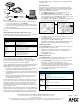
FIG. 2
ViewPoint connectors
VPA-DS Specifications
Dimensions (HWD) 4.83" x 8.26" x 7.62" (122.7 mm x 209.8 mm x 193.4 mm)
Environmental operating range:
Temperature • 50 °F to 104 °F (10 °C to 40 °C)
Humidity • 0% to 90% non-condensing
Power 2.8 A @ 12 VDC
Indicators:
Yellow LED • Indicates ViewPoint connected to ViewPort Docking Station
Green LED • Indicates spare battery is fully charged
Red LED • Indicates spare battery is charging
Options:
Power supply • 2.8 A @ 12 VDC power supply
Battery • VPA-BP ViewPoint Rechargeable Battery
(NiMH, 3.7 Amp @ 7.2 VDC)
Power
jack
Programming
jack
Stereo
DB-9 connector
Connect FG10-817 to cable FG10-727
ViewPoint
to PC
programming
cable
male
plug
Serial Commands
CALIBRATE
Starts touch
panel calibra-
tion.
Syntax:
"CALIBRATE"
Example:
CALIBRATE
Starts the calibration sequence mode on the touch panel.
SETUP
Puts the touch
panel on the
Setup Page.
Syntax:
"SETUP"
Example:
SETUP
Flips the touch panel to the Setup page.
ZAP!
Clears all
memory.
Syntax:
"ZAP!"
Example:
ZAP!
Clears all memory and erases all buttons, pages, drawings, and symbols.
FIG. 3 Setup page FIG. 4 Protected Setup page