Operation/Reference Guide TPI-PRO Total Presentation Interface - Pro Edition TPI-PRO-4 TPI-PRO-2 To u ch P a n e l I nt er f a c e L a s t Re v is e d: 11 /1 2 /20 0 8
AMX Limited Warranty and Disclaimer This Limited Warranty and Disclaimer extends only to products purchased directly from AMX or an AMX Authorized Partner which include AMX Dealers, Distributors, VIP’s or other AMX authorized entity.
Table of Contents Table of Contents Overview ............................................................................................................1 TPI-PRO-4 Front and Rear Components ................................................................... 2 TPI-PRO-2 Front and Rear Components ................................................................... 2 TPI-PRO Specifications.............................................................................................. 3 Installation ...........
Table of Contents Master Connection section - NetLinx Master Ethernet IP Address - URL Mode ............ 35 Master Connection section - NetLinx Master Ethernet IP Address - Listen Mode ......... 36 Master Connection section - NetLinx Master Ethernet IP Address - Auto Mode........... 37 Master Connection section - NetLinx Master Ethernet IP Address - NDP (UDP) Mode ...................................................................................
Table of Contents Panel Statistics Page ..................................................................................................... 70 Checking the Panel Statistics ........................................................................................ 71 Refreshing the Panel Statistics ...................................................................................... 71 Clearing the Panel Statistics..........................................................................................
Table of Contents iv Total Presentation Interface - Pro Edition
Overview Overview The TPI-PRO Total Presentation Interface - Pro Edition serves as a video switcher that allows users to incorporate large-scale touch-screen technology from a variety of manufacturers into an AMX NetLinx controlled system. With the TPI-PRO, multiple video and RGB sources can be simultaneously delivered to a display, then controlled and managed via a connected touch monitor or through send commands on the NetLinx Controller.
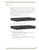
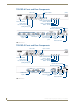
Overview TPI-PRO-4 Front and Rear Components Status LED Input 1-4 LEDs (Front) Button - RESOLUTION Button - TOUCH Button - CALIBRATE Button - SETUP Power switch/LED 2 USB (Type-A) Host Interface ports Serial (Configuration) port RS-232 Touch Input port Ethernet port (RJ-45) VGA Outputs 1-2 VIDEO/VGA Inputs 1-4 2 USB (Type-A) ports 4 USB (Type-B) Source Interface ports (Rear) Stereo Output Power Connector FIG.
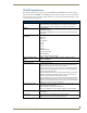
Overview TPI-PRO Specifications The following table lists the specifications for the TPI-PRO-4 and TPI-PRO-2. Note that the primary difference between the TPI-PRO-4 and TPI-PRO-2 is in the number of inputs. In terms of functionality and specifications, they are otherwise identical. Therefore, the specifications listed below apply to both versions, unless specifically noted. TPI-PRO Specifications Power Requirements: • Constant current draw: 2.6 A @ 12 VDC • The PSN6.
Overview TPI-PRO Specifications (Cont.) Input LEDs Yellow LEDs indicate a valid input signal on each source input (1-4 on the TPI-PRO-4, 1-2 on the TPI-PRO-2). Buttons Four white buttons provide access to the following configuration options: • RESOLUTION: Opens a screen used to select the TPI-PRO output video signal resolution, ranging from 640 x 480@60Hz to 1920 x 1200@60Hz. This output resolution cannot be greater than the resolution on the connected panel.
Overview TPI-PRO Specifications (Cont.) Serial Touch Drivers: For an updated list of available serial touch input drivers that are selectable by using the TOUCH button on the front panel of the TPI-PRO, visit www.amx.com. Refer to the List of Available Pixel Display and Refresh Rates section on page 140 for a more detailed list of Touch Monitors that have been tested with the TPI-Pro. USB Drivers: USB Touch drivers are automatically loaded when the USB Touch Monitor is detected. Refer to www.amx.
Overview TPI-PRO Specifications (Cont.) Other AMX Equipment: • PSN6.5: Power Supply with 3.
Installation Installation Overview The TPI-PRO comes included with rack ears that can be rotated 90° in any direction to accommodate several different mounting options, including tabletop, under/over the table, and vertical wall mounting. Rotate the mounting brackets to mount the TPI-PRO on top of a flat surface, under-table, or vertically. Mounting the TPI-PRO into an 19" Equipment Rack The TPI-PRO occupies one rack unit in a standard 19" equipment rack.
Installation Ventilation ALWAYS ensure that the rack enclosure is adequately ventilated. The maximum operating ambient temperature is 40°C. Sufficient airflow must be achieved (by convection or forced-air cooling) to satisfy the ventilation requirements of all the items of equipment installed within the rack. Never restrict the airflow through the device’s fan or vents. When installing equipment into a rack, distribute the units evenly.
Installation TPI-PRO Total Presentation Interface - Pro Edition 9
Installation 10 TPI-PRO Total Presentation Interface - Pro Edition
Wiring and Device Connections Wiring and Device Connections Overview Most device connections are made via the ports on the rear panel of the TPI-PRO (FIG. 6). VIDEO/VGA INPUTS - These HD-15 connectors accept source video from up to four Source devices. Connect to the output ports on the Source devices with the appropriate cable according to the source signal type. VGA OUTPUTS - These HD-15 connectors distribute TPI-PRO video to up to two display devices.
Wiring and Device Connections System Diagrams The following System Diagrams illustrate the most common applications for the TPI-PRO. For detailed pinout descriptions for each connector on the TPI-PRO, refer to the Connector Details and Pinout Configurations section on page 17. Example 1 (TOUCH INPUT) The example below displays a typical installation using a touch panel to display output from a video source (in this case, a PC.
Wiring and Device Connections 6. Cycle power the unit. Cycle powering the unit allows it to detect the new configuration. Example 2 (Mouse Pass-Thru Control) The example below displays a typical installation for using a touch panel for mouse pass-thru control. PC Signal video feed from the computer to the monitor through the TPI-PRO.
Wiring and Device Connections The two USB connectors on the rear of the TPI-PRO are used to provide signals from a keyboard and/or mouse. The Type-B USB connection on the TPI-PRO is used for communication between the TPI-PRO and the computer. Using a USB hub may cause functionality issues with all USB ports on the TPI-PRO. AMX recommends you do not use a USB hub to connect multiple USB devices to the TPI-PRO. USB 2.0 support is required for all USB devices.
Wiring and Device Connections 10. Use the CRT’s video adjust buttons to align the incoming video signal to fit into the available screen area. Initially positioning the TPI-PRO incoming video can reduce any later adjustments of the video through the RGB Setup page (H-position, V-position, H-size, etc.) Example 3 (Using a Touch Panel for Mouse / Touch Pass-Thru Control) The example below displays a typical installation for using a touch panel for mouse and touch pass-thru control.
Wiring and Device Connections Follow these steps to configure the TPI-PRO to use a touch panel for touch and mouse pass-thru control: 1. Discharge any acquired static electricity by touching a grounded metal object. 2. Disconnect any incoming power connector from the rear of the TPI-PRO. 3. Connect a USB mouse to the TPI-PRO unit. 4. Connect a USB cable from a rear USB connector port (on the computer) to the Type-B USB device port input connector on the rear of the TPI-PRO. 5.
Wiring and Device Connections Connector Details and Pinout Configurations The following sections describe in detail each of the connectors on the the TPI-PRO: VIDEO/VGA INPUT Connectors FIG. 11 VIDEO/VGA INPUT Connectors The Video/VGA Input connectors are used for source input devices (4 on the TPI-PRO-4, 2 on the TPI-PRO-2). Each connector supports VGA graphics, S-video, composite video, and component video. The TPI-PRO routes the video from the connected input devices to any connected output devices.
Wiring and Device Connections The following tables list the VGA OUT HD-15 connector pinouts.
Wiring and Device Connections The following table lists the pinout configuration for HD-15 connector to Component (RGB) connectors: VGA IN to Component (RGB) Pinouts VGA Pin VGA Signal Component Signal Red RCA 1 Red Pr signal center pin 2 Green Y signal 3 Blue Pb signal 4 Sense 2 5 GND 6 RAGND Pr - Return 7 GAGND Y - Return 8 BAGND Pb - Return 9 N/A 10 SAGND 11 Sense 0 12 Sense 1 13 HSYNC 14 VSYNC 15 Sense 3 Green RCA Blue RCA center pin center pin shield shield
Wiring and Device Connections SOURCE KEYBOARD/MOUSE (USB-Type B) Ports FIG. 13 SOURCE KEYBOARD/MOUSE (USB-Type B) Ports You can connect up to four USB Type-B Host PC connections for TOUCH, Mouse and Keyboard pass-through to the PC (two on the TPI-PRO-2, four on the TPI-PRO-4) via the SOURCE KEYBOARD/ MOUSE USB connectors. If you experience problems introducing new devices, you can install the drivers on a remote PC according to manufacturer suggestions with the device connected directly to the remote PC.
Wiring and Device Connections TOUCH INPUT (DB9) Port FIG. 14 TOUCH INPUT (DB9) Port The RS-232 (DB9) 9-pin serial port provides connectivity to a pointer device (i.e. touch screen) that requires a serial connection. The following table lists the RS-232 connector pinouts.
Wiring and Device Connections ETHERNET (RJ-45) Port FIG. 15 ETHERNET (RJ-45) Port The RJ-45 port provides 10/100 Mbps communication communicates with the NetLinx Master (via ICSP protocol over Ethernet). The Ethernet port automatically negotiates the connection speed (10 Mbps or 100 Mbps), and whether to use half duplex or full duplex mode. This communication is reflected via the front ICSP LED. FIG. 16 describes the blink activity for the ETHERNET 10/100 Base-T RJ-45 connector and cable.
Wiring and Device Connections Power (2-Pin Captive Wire) Connector FIG. 18 Power (2-Pin Captive Wire) Connector The TPI-PRO requires a 12 VDC-compliant power supply to provide power to the TPI-PRO via the 2-pin 3.5 mm mini-Phoenix PWR connector. The incoming PWR and GND wires from the power supply must be connected to the corresponding locations within the PWR connector. Do not connect power to the TPI-PRO until wiring is complete. These units should only have one source of incoming power.
Wiring and Device Connections 24 TPI-PRO Total Presentation Interface - Pro Edition
TPI-PRO and Panel Interface Setup TPI-PRO and Panel Interface Setup The information contained within this section refers to the procedures necessary to set up the TPI-PRO resolution, assign a touch driver, and calibrate the driver for use with a connected touch panel. Verify you are using the latest NetLinx Master firmware. Verify you are using the latest TPI-PRO firmware. Verify the NetLinx Studio program you are using is version 2.4 or higher. Verify the TPDesign4 program you are using is version 2.
TPI-PRO and Panel Interface Setup Setting the Output Resolution on the TPI-PRO To correct the problem of an OUT OF RANGE message, the TPI-PRO output resolution must be set to match the same output pixel resolution and refresh rate set on the connected panel/monitor. The default TPI-PRO output resolution is 1280 x 1024@60Hz. Use the front panel RESOLUTION button to alter the outgoing resolution (for a maximum of 1920 x 1200@60 Hz). 1. Press the RESOLUTION button on the front panel.
TPI-PRO and Panel Interface Setup 4. Press and hold-down firmly the RESOLUTION button to save the resolution setting. A message stating: "Please wait, loading new resolution..." appears to indicate the new resolution being is saved. The Resolution Setup page then displays and exits the resolution setup process. There is then some shifting of the defaulted Main page (which was developed for a 1280 x 1024 resolution). 5.
TPI-PRO and Panel Interface Setup Calibrating the TPI-PRO Using a USB Input 1. Connect a USB cable from a touch panel to one of the Type-A USB ports on the front or back of the TPI-PRO. 2. Reboot the TPI-PRO by pressing the power button on the unit so the unit can detect the new hardware. 3. Press the CALIBRATE button on the front panel. This process opens a calibration page that uses a series of crosshair coordinate intersections to calibrate the touch panel (using the newly selected touch driver).
TPI-PRO and Panel Interface Setup 6. Press the Protected Setup button (located on the lower-left of the panel page) to open the Protected Setup page. 7. Enter 1988 into the Keypad’s password field and press Done when finished. 8. Press the on-screen Reboot button to cycle power to the TPI-PRO and incorporate the new settings. The touch monitor goes blank for a few seconds during the reboot process. You can also use a mouse to press the on-screen Reboot button. 9.
TPI-PRO and Panel Interface Setup 30 TPI-PRO Total Presentation Interface - Pro Edition
Configuring Communication Configuring Communication Communication between the TPI-PRO and the NetLinx Master consists of using an Ethernet connection (DHCP or Static IP). If you are currently using a static IP Address, continue with the IP Settings section Configuring a Static IP Address over Ethernet section on page 33. Before commencing, verify you are using the latest NetLinx Master firmware. Verify the NetLinx Studio program being used is version 2.4 or higher. Setting up the TPI-PRO Device Number 1.
Configuring Communication FIG. 23 Protected Setup page with Keypad 7. Use the Baud Rate Up/Down arrows to cycle through the available baud rates for TPI-PRO serial communication to the connected PC. The default is 38400. Before continuing, open NetLinx Studio. This program assists in developing a System Number, Master IP/URL, and Master Port number. Refer to your NetLinx Master’s instruction manual for more information. 8. Obtain the System Number and Master IP Address from NetLinx Studio.
Configuring Communication Configuring a Wired Ethernet Connection It is necessary to tell the panel with which Master it should be communicating. "Pointing to a Master" is configured via the System Connection page where you configure the IP Address, System Number, and Username/Password information assigned to the target Master. Until you configure these parameters, your Connection Status icon remains red, indicating there is no current connection to a Master.
Configuring Communication 10. Press the Domain field to open a keyboard, enter the resolvable domain address (this is provided by your System Administrator and equates to a unique Internet name for the TPI-PRO.) Press Done when complete. 11. Press the Back button to return to the Protected Setup page. 12. Press the on-screen Reboot button to both save any changes and restart the TPI-PRO. 13.
Configuring Communication 4. Connect the terminal end of the PSN power cable to the 12 VDC power connector on the rear of the TPI-PRO. 5. Verify the green Ethernet LED on the rear Ethernet port on both the Master and TPI-PRO are illuminated, indicating a proper connection. 6. Verify the green Ethernet LED on the rear Ethernet port on the Master is illuminated, indicating a proper connection. 7. Verify the yellow LED on the rear Ethernet port on the Master is blinking, indicating communication. 8.
Configuring Communication 7. Press the on-screen Reboot button to both save any changes and restart the TPI-PRO. Master Connection section - NetLinx Master Ethernet IP Address - Listen Mode In this mode, you must add the TPI-PRO IP address into the URL List of the Master (using NetLinx Studio). This mode sets the TPI-PRO to "listen" for connections from the Master (using the TPI-PRO’s IP from its URL list). 1.
Configuring Communication Master Connection section - NetLinx Master Ethernet IP Address - Auto Mode In this mode, enter the System Number of the NetLinx Master. This mode instructs the TPI-PRO to search for a Master that uses the same System Number (assigned within the Master Connection section) and resides on the same Subnet as the TPI-PRO. 1. Press the Mode field until the option cycles to Auto. 2.
Configuring Communication Master Connection section - NetLinx Master Ethernet IP Address - URL (UDP) Mode In this mode, enter the System Number (zero for an unknown System Number) and the IP/URL of the Master (Master Port Number is defaulted to 1319). 1. Press the Mode field until the option cycles to URL (UDP). By selecting URL (UDP), the System Number field becomes read-only (grey) because the panel pulls this value directly from the communicating target Master. 2.
Configuring Communication 5. Press the G4 Web Control button to open the G4 Web Control page (FIG. 27). FIG. 27 G4 Web Control page 6. Press the Enable/Enabled button until it toggles to Enabled (light blue color). 7. The Network Interface Select field is read-only for the TPI-PRO and uses Wired as the default method of communication to the web. Wired is used when a direct Ethernet connection is being used for communication to the web.
Configuring Communication Using your NetLinx Master to Control the Unit Refer to your particular NetLinx Master’s instruction manual for detailed information on how to download the latest firmware from www.amx.com. Once the Master’s IP Address has been set through NetLinx Studio (version 2.4 or higher): 1. Launch your web browser. 2. Enter the IP address of the target Master (ex: http://198.198.99.99) into the web browser’s Address field. 3.
Configuring Communication 7. Click on the G4 panel name link associated with the target panel. A secondary web browser window then appears on the screen (FIG. 29). The G4 Web Control application is sent by the TPI-PRO to the computer that is used for communication. Once the application is installed, this popup will no longer appear. This popup will only appear if you are connecting to the target panel using a different computer. FIG. 29 Web Control VNC installation and Password entry screens 8.
Configuring Communication The secondary window becomes populated with the same G4 page being displayed on the target G4 panel. A small circle appears within the on-screen G4 panel page and corresponds to the location of the mouse cursor. A left-mouse click on the computer-displayed panel page equates to an actual touch on the target G4 panel page.
Upgrading TPI-PRO Firmware Upgrading TPI-PRO Firmware Before beginning the Upgrade process: Setup and configure your NetLinx Master. Refer to your particular NetLinx Master instruction manual for detailed setup procedures. Select the correct resolution, touch drivers, and calibrate the TPI-PRO. Refer to the Calibrating the TPI-PRO Using a USB Input section on page 28. Refer to the NetLinx Studio version 2.4 or higher Help file for more information on uploading files via Ethernet.
Upgrading TPI-PRO Firmware List of previously saved IP addresses FIG. 31 Assigning Communication Settings and TCP/IP Settings 4. Click the Communications Settings button to open the Communications Settings dialog box. 5. Click on the NetLinx Master option button in the Platform Selection section to indicate that you are working with a NetLinx Master (such as the NXC-ME260/64 or NI-Series of Integrated Controllers). 6.
Upgrading TPI-PRO Firmware Step 2: Prepare the TPI-PRO for communication via an IP address 1. Press the Mode field until the choice cycles to URL. By selecting URL, the System Number field becomes read-only (grey) because the panel pulls this value directly from the communicating target Master (virtual or not). A virtual Master system value can be set within the active AMX software applications such as: NetLinx Studio, TPD4, or IREdit. 2.
Upgrading TPI-PRO Firmware 7. Select Tools > Firmware Transfers > Send to NetLinx Device from the Main menu to open the Send to NetLinx Device dialog box (FIG. 33). Verify the TPI-PRO’s System and Device number values match those values listed within the System folder in the OnLine Tree tab of the Workspace window. Selected firmware file Description field for selected .kit file Firmware download status Device number and System number must match the values listed in the Workspace window. FIG.
Firmware Pages and Descriptions Firmware Pages and Descriptions This section describes each G4 firmware page and their specific functional elements. The TPI-PRO is a G4 device that utilizes specific G4 pages. Setup Navigation Buttons The G4 Setup Navigation Buttons (FIG. 34) appear on the left of the panel screen when the Setup page is currently active. FIG.
Firmware Pages and Descriptions G4 Setup Navigation Button Elements (Cont.) Video Press the Video Adjustment button to access the main video page where you can set the video properties for incoming signal. • The displayed page is associated to the HD-15 port being used. • The TPI-PRO-4 can use any combination of up to four (4) source inputs. The TPI-PRO-2 can use any combination of up to two (2) source inputs. • Refer to the Video Settings Page section on page 54 for more detailed information.
Firmware Pages and Descriptions Setup Page Elements (Cont.) Connection Status Displays whether the G4 device is communicating externally, the encryption status of the communicating Master, what connection type is being used (Ethernet), and of which System the unit is a part. This visual display of the connection status is also reflected at the upper-right of each firmware page.
Firmware Pages and Descriptions Project Information Page The Project Information page displays the TPDesign4 (TPD4) project file properties currently loaded on the selected TPI-PRO (FIG. 36). Refer to the TPDesign4 Touch Panel Program instruction manual for more specific information on uploading TPDesign4 files to a panel. Sample TPD4 Project Properties dialog box FIG.
Firmware Pages and Descriptions Panel Information Page The Panel Information page (FIG. 37) centers around TPI-PRO properties such as resolution used, on-board memory, firmware, address/channel information, and string information. This information is retrieved from the TPI-PRO unit FIG.
Firmware Pages and Descriptions Panel Information Page Elements (Cont.) Power Up Page Displays the first touch panel page assigned for display after the device is powered-up. • This information is taken from the TPD4 project file. • Most projects begin with a Main page. Start Up String Displays the start-up string. Wake Up String Displays the wake up string used after an activation from a timeout. Sleep String Displays the sleep string used during the device’s sleep mode.
Firmware Pages and Descriptions Time & Date Setup Page Elements (Cont.) Time Display fields These fields display the time in three formats: STANDARD, STANDARD AM/PM, and 24 HOUR. Date Display fields These fields display the calendar date information in several different formats. Set Date/Time This section provides a user with both UP/DN arrow buttons to alter the Master’s calendar date and time. The blue circle indicates which field is currently selected.
Firmware Pages and Descriptions Audio Settings Page Elements (Cont.) Master Volume This section allows you to adjust the current sound level on the unit’s internal speaker: • Use the UP/DN buttons to adjust the volume output on the internal speakers (range = 0 - 100). • The Internal Sound Level bargraph indicates the current sound level. • The Mute button mutes the volume. • The Play Test button plays a test WAV/MP3 file over the internal speakers.
Firmware Pages and Descriptions The elements of the Video Settings page are described in the table below: Video Settings Page Elements Back Saves the changes and returns you to the previously active touch panel page. Connection Status icon This visual display of the connection status allows the user to have a current update of the TPI-PRO’s connection status regardless of what page is currently active.
Firmware Pages and Descriptions Video Settings Page Elements (Cont.) Undo Changes The Undo Changes button disregards any changes made on the page since the last settings were saved. Save Settings The Save Settings button saves any changes made to this page. Video Settings - RGB Adjustment Page The RGB Adjustment page (FIG. 41) sets the RGB properties of the incoming signal.
Firmware Pages and Descriptions Adjusting the Incoming Image on the Video Adjustment Page After opening the Video Adjustment page, you can select any of the available source inputs by selecting the corresponding tab at the top of the screen. If the selected source input is receiving an image, this image is displayed in the incoming signal area. You can adjust the incoming image by using the video setting on the right side of the screen. Perform the following steps to adjust these settings: 1.
Firmware Pages and Descriptions Protected Setup Navigation Buttons The Protected Setup Navigation Buttons (FIG. 42) appear on the left of the screen when the Protected Setup page is currently active. FIG.
Firmware Pages and Descriptions Protected Setup Page The Protected Setup page (FIG. 43) centers around the properties used by the TPI-PRO to communicate with the NetLinx Master. Enter the factory default password (1988) into the password keypad to access this page. FIG. 43 Protected Setup page The elements of the Protected Setup page are described in the table below: Protected Setup Page Elements Back Saves the changes and returns you to the previously active touch panel page.
Firmware Pages and Descriptions Protected Setup Page Elements (Cont.) System Recovery Allows you to either reset the TPI-PRO to factory default settings and/or wipe out all existing touch panel pages: • The Reset System Settings button allows a user to wipe out all current configuration parameters on the TPI-PRO (such as IP Addresses, Device Number assignments, Passwords, and other presets). - Pressing this button launches a confirmation dialog box (FIG. 44) which asks you to confirm your selection.
Firmware Pages and Descriptions G4 Web Control Page The G4 Web Control page (FIG. 46) centers around enabling and disabling both the display and control of your TPI-PRO (via the web). An external PC running a VNC client (installed during the initial communication to the G4 device) makes this possible. FIG. 46 G4 Web Control page Each G4 device supports the open standard Virtual Network Computing (VNC) interface.
Firmware Pages and Descriptions G4 Web Control Page Elements (Cont.) G4 Web Control Settings Sets the IP communication values for the TPI-PRO and contains: Enable/Enabled • The Enable/Enabled button allows you to toggle between the two G4 activation settings: - Enable - deactivates the G4 Web Control feature on the TPI-PRO. - Enabled - activates the G4 Web Control feature on the TPI-PRO and allows an external PC running a VNC client to access the unit, after the remaining fields are configured.
Firmware Pages and Descriptions Password Setup Page The Password Setup page (FIG. 47) centers around the properties used to assign passwords for the panel pages. FIG. 47 Password Setup page The elements of the Password Setup page are described in the table below: Password Setup Page Elements Back Saves the changes and returns you to the previously active touch panel page.
Firmware Pages and Descriptions Press and hold the front panel CALIBRATE button to access the Calibration page. Press the crosshairs to calibrate the panel and return to the last open firmware page. System Settings Page The System Settings page (FIG. 49) sets the DNS Address information with its corresponding IP communication parameters, NetLinx Master communication settings, and reads the device number assigned to the G4 device.
Firmware Pages and Descriptions System Settings Page Elements (Cont.) IP Settings (Cont.) Primary DNS Sets the address of the primary DNS server being used by the TPI-PRO for host name lookups. • DNS (Domain Name System) is software that lets users locate computers on a local network or the Internet (TCP/IP network) by host and domain. The DNS server maintains a database of host names for its’ domain and their corresponding IP Addresses. Secondary DNS Sets the secondary DNS value to the TPI-PRO.
Firmware Pages and Descriptions Cache Page The Cache page (FIG. 50) configures the allocation of memory for image caching. The G4 graphics engine caches images to decrease load time of previously viewed images. RAM caching is always enabled, and images (both static and dynamic) are stored in the RAM cache as they are viewed. The size of RAM cache is automatically configured to take into account available memory versus memory that may be needed by the panel later.
Firmware Pages and Descriptions The elements of the Cache page are described in the following table: Image Caching Page Elements Back Saves all changes and returns to the previous page. Connection Status icon The icon in the upper-right corner of each Setup page shows online/offline state of the panel to the master. • Bright red - disconnected • Bright green - connected. Blinks when a blink message is received to dark green every 5 seconds for half a second then go back to bright green.
Firmware Pages and Descriptions Setting the image cache In the Protected Setup page: 1. Press the Other Settings button to open an options slide bar. 2. Press the Cache button in the slide bar. The Cache page opens. 3. Set the cache expiration in the field Flash/RAM Cache Expires. The Up and Down arrows increment through the available time frames. 4. Press the Enable button to turn on image caching. The button appears illuminated when enabled.
Firmware Pages and Descriptions The elements of the Panel Logs page are described in the following table: Panel Logs Page Back Saves all changes and returns to the previous page. Connection Status icon The icon in the upper-right corner of each Setup page shows online/offline state of the panel to the master. • Bright red - disconnected • Bright green - connected. Blinks when a blink message is received to dark green every 5 seconds for half a second then go back to bright green.
Firmware Pages and Descriptions Panel Statistics Page The options on the Panel Statistics page allow you to track the connection status for the panel. The Panel Statistics page tracks ICSP messages, Blink messages, Ethernet connection statistics, and Wireless connection statistics (FIG. 52). FIG. 52 Panel Statistics page The elements of the Panel Statistics page are described in the following table: Panel Statistics Page Back Saves all changes and returns to the previous page.
Firmware Pages and Descriptions Checking the Panel Statistics 1. Press the Tools button in the Protected Setup Navigation Buttons section. This opens the Tools menu. 2. Within the Tools menu, press the Panel Statistics button. All connection statistics are contained on this page, e.g., Received, Processed, and Dropped ICSP Messages. Refreshing the Panel Statistics 1. Press the Tools button in the Protected Setup Navigation Buttons section. This opens the Tools menu. 2.
Firmware Pages and Descriptions Connection Utility Page The options on the Connection Utility page allows you to view query and response statistics for your connection. FIG. 53 Connection Utility page The elements of the Connection Utility page are described in the following table: Connection Utility Page Close Saves all changes and returns to the previous page. Connection Status icon The icon in the upper-right corner of each Setup page shows online/offline state of the panel to the master.
Firmware Pages and Descriptions Connection Utility Page (Cont.) Signal Strength This indicator displays a description of the signal strength from the Wireless Access Point connection in real time (None, Poor, Fair, Good, Very Good, and Excellent). SNR (Signal Noise Ratio) is a measure of the relative strength of a wireless RF connection. Given this value and the link quality above, you can determine the noise level component of the SNR.
Firmware Pages and Descriptions 74 TPI-PRO Total Presentation Interface - Pro Edition
Programming Programming You can program a touch panel using the commands in this section to perform a wide variety of operations using Send_Commands and variable text commands. Refer to the NetLinx Programming Language instruction manual for complete information. Verify you are using the latest NetLinx Master firmware. Verify the NetLinx Studio program being used is version 2.4 or higher and TPD4 is version 2.8 or higher.
Programming Page Commands (Cont.) @CPG Syntax: Clear all popup pages from specified popup group. Variable: "'@CPG-'" popup group = 1 - 50 ASCII characters. Name of the popup group. Example: SEND_COMMAND Panel,"'@CPG-Group1'" Clears all popup pages from the popup group ’Group1’. @DPG Delete a specific popup page from specified popup group if it exists. Syntax: "'@DPG-;'" Variable: popup page name = 1 - 50 ASCII characters. Name of the popup page.
Programming Page Commands (Cont.) @PHT Syntax: Set the hide effect time for the specified popup page. Variable: "'@PHT-;'" popup page name = 1 - 50 ASCII characters. Name of the page on which the popup is displayed. hide effect time = Given in 1/10ths of a second. Example: SEND_COMMAND Panel,"'@PHT-Popup1;50'" Sets the Popup1 hide effect time to 5 seconds. @PPA Close all popups on a specified page. If the page name is empty, the current page is used.
Programming Page Commands (Cont.) @PPK Kill a specific popup page from all pages. Kill refers to the deactivating (Off) of a popup window from all pages. If the pop-up page is part of a group, the whole group is deactivated. This command works in the same way as the 'Clear Group' command in TPDesign4. Syntax: "'@PPK-'" Variable: popup page name = 1 - 50 ASCII characters. Name of the popup page. Example: SEND_COMMAND Panel,"'@PPK-Popup1'" Kills the popup page ’Popup1’ on all pages.
Programming Page Commands (Cont.) @PPT If timeout is empty, popup page will clear the timeout. Set a specific popup page to timeout within a specified time. Syntax: "'@PPT-;'" Variable: popup page name = 1 - 50 ASCII characters. Name of the popup page. timeout = Timeout duration in 1/10ths of a second. Example: SEND_COMMAND Panel,"'@PPT-Popup1;30'" Sets the popup page ’Popup1’ to timeout within 3 seconds. @PPX Same as a 'Clear All' command in TPDesign 4.
Programming Page Commands (Cont.) PAGE Flip to a specified page. Flips to a page with a specified page name. If the page is currently active, it will not redraw the page. Syntax: "'PAGE-'" Variable: page name = 1 - 50 ASCII characters. Name of the page on which the popup is displayed. Example: SEND_COMMAND Panel,"'PAGE-Page1'" Flips to page1. PPOF Deactivate a specific popup page on either a specified page or the current page.
Programming Page Commands (Cont.) PPON Activate a specific popup page to launch on either a specified page or the current page. If the page name is empty, the current page is used (see example 2). If the popup page is already On, do not re-draw it. This command works in the same way as the ’Show Popup’ command in TPDesign4. Syntax: "'PPON-;'" Variable: popup page name = 1 - 50 ASCII characters. Name of the popup page. page name = 1 - 50 ASCII characters.
Programming RGB Values for all 88 Basic Colors (Cont.) 82 Index No.
Programming RGB Values for all 88 Basic Colors (Cont.) Index No.
Programming You must import fonts into a TPDesign4 project file. The font ID numbers are assigned by TPDesign4. These values are also listed in the Generate Programmer’s Report. Border styles The TPDesign4 Touch Panel Design program has pre-set border styles that are user selectable. TPD4 border styles can ONLY be changed by using the name.
Programming TPD4 Border Styles by Name (Cont.
Programming "^" Button Commands These Button Commands are not case sensitive. All commands that begin with "^" have the capability of assigning a variable text address range and button state range. A device must first be defined in the NetLinx programming language with values for the Device: Port : System (in all programming examples - Panel is used in place of these values). Variable text ranges allow you to target one or more variable text channels in a single command.
Programming "^" Button Commands (Cont.) ^BAT Syntax: Append non-unicode text. Variable: "'^BAT-,
Programming "^" Button Commands (Cont.) ^BCF This command works only if the specified fill color is not the same as the current color. Set the fill color to the specified color. Note: Color can be assigned by color name (without spaces), number or R,G,B value (RRGGBB or RRGGBBAA). Syntax: "'^BCF-,
Programming "^" Button Commands (Cont.) ^BDO Determines what order each layer of the button is drawn. Set the button draw order. Syntax: "'^BDO-,
Programming "^" Button Commands (Cont.) ^BIM Syntax: Set the input "'^BIM-,'" mask for the Variable: specified address. variable text address range = 1 - 4000. input mask = Refer to the Text Area Input Masking section on page 136 for character types. Example: SEND_COMMAND Panel,"'^BIM-500,AAAAAAAAAA'" Sets the input mask to ten ’A’ characters, that are required, to either a letter or digit (entry is required).
Programming "^" Button Commands (Cont.) ^BMC Button copy command. Copy attributes of the source button to all the destination buttons. Note that the source is a single button state. Each state must be copied as a separate command. The section represents what attributes will be copied. All codes are 2 character pairs that can be separated by comma, space, percent or just ran together.
Programming "^" Button Commands (Cont.) ^BMF Set any/all button parameters by sending embedded codes and data. Syntax: "'^BMF-,
Programming "^" Button Commands (Cont.) ^BMF (Cont.) For some of these commands and values, refer to the RGB Values for all 88 Basic Colors table on page 81. ’%CF’ = Set Fill Color. ’%CB’ = Set Border Color. ’%CT’ = Set Text Color. ’%SW<1 or 0>’ = Show/hide a button. ’%ST